Subaru Legacy IV (2008 year). Service manual — part 173

EN(H4SO)(diag)-295
Diagnostic Procedure with Diagnostic Trouble Code (DTC)
ENGINE (DIAGNOSTICS)
6
CHECK HARNESS BETWEEN ECM AND
ELECTRONIC THROTTLE CONTROL.
1) Turn the ignition switch to OFF.
2) Disconnect the connectors from ECM.
3) Measure the resistance between ECM con-
nectors.
Connector & terminal
(B134) No. 19 — (B134) No. 18:
(B134) No. 19 — (B134) No. 28:
Is the resistance 1 M
: or
more?
Repair poor con-
tact of the elec-
tronic throttle
control connector.
Replace the elec-
tronic throttle con-
trol if defective.
<Ref. to
FU(H4SO)-12,
Throttle Body.>
Repair the short
circuit to power in
the harness
between ECM and
electronic throttle
control connector.
Step
Check
Yes
No
EN(H4SO)(diag)-296
Diagnostic Procedure with Diagnostic Trouble Code (DTC)
ENGINE (DIAGNOSTICS)
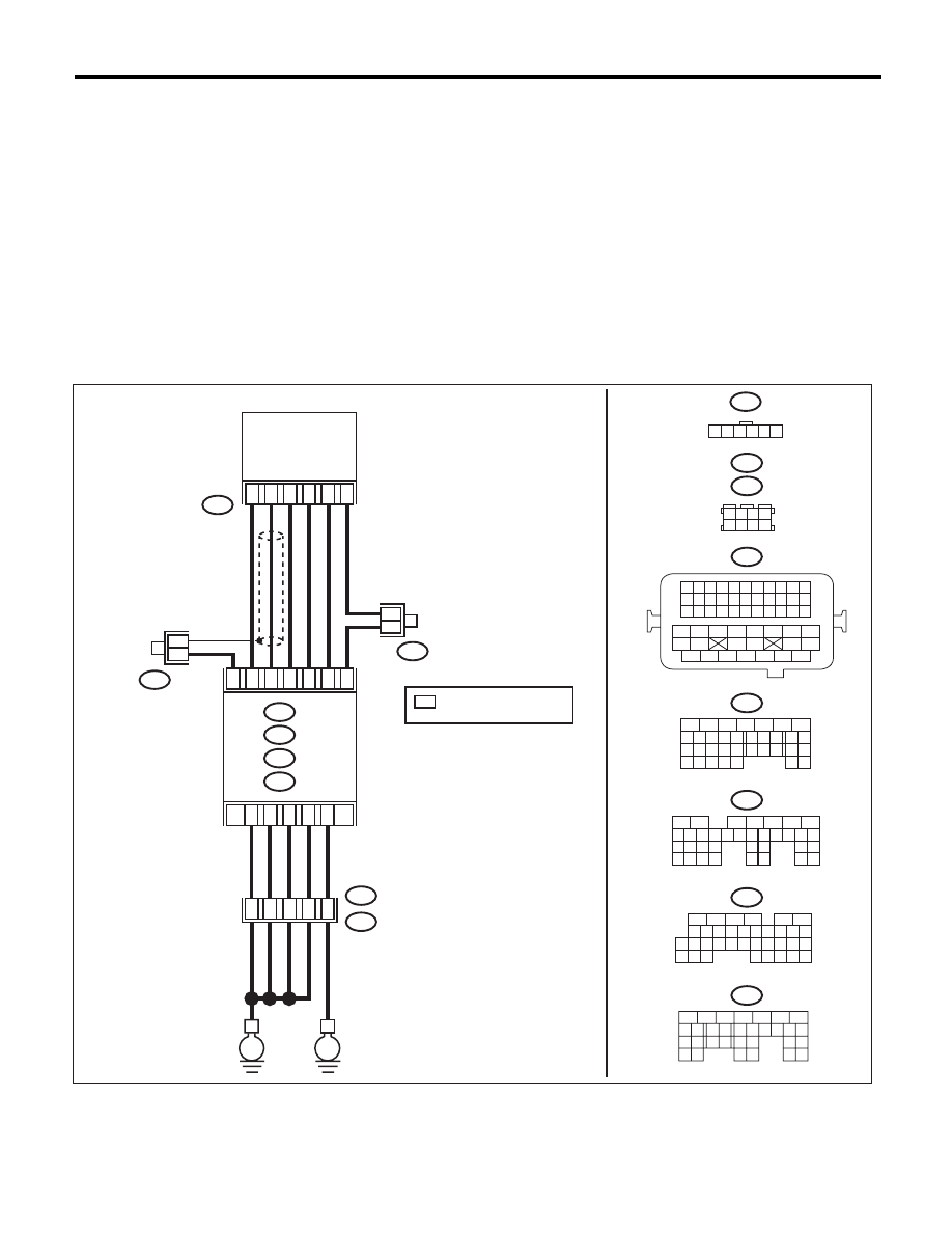
DJ:DTC P2138 THROTTLE/PEDAL POSITION SENSOR/SWITCH “D”/“E” VOLTAGE
CORRELATION
DTC DETECTING CONDITION:
• Immediately at fault recognition
• GENERAL DESCRIPTION <Ref. to GD(H4SO)-196, DTC P2138 THROTTLE/PEDAL POSITION SEN-
SOR/SWITCH “D”/“E” VOLTAGE CORRELATION, Diagnostic Trouble Code (DTC) Detecting Criteria.>
TROUBLE SYMPTOM:
• Improper idling
• Poor driving performance
CAUTION:
After repair or replacement of faulty parts, perform Clear Memory Mode <Ref. to EN(H4SO)(diag)-50,
OPERATION, Clear Memory Mode.>, and Inspection Mode <Ref. to EN(H4SO)(diag)-41, PROCEDURE,
Inspection Mode.>.
WIRING DIAGRAM:
EN-06844
B315
E
C:
ECM
B136
B137
D:
B83
B315
*
*
4
6
5
1
3
2
D1
D2
1 2 3 4 5 6
B21
E2
D3
B122
1 2 3 4
5 6 7 8
B21
1 2 3 4
12 13 14 15
5 6 7 8
16 17 18 19
9 10 11
20 21 22
23 24 25 26 27 28 29 30 31 32 33
35
34
37
36
39
38
41
40
43
42
44
45
47
46
49
48
51
50
53
52
54
B137
5
6
7
8
2
1
9
4
3
10
22 23
11 12 13 14 15
24 25
26
16 17
18 19 20 21
27
28 29
30 31
B136
5
6
7 8
2
1
9
4
3
10
24
22 23
25
11 12 13 14 15
26 27
28
16
17 18 19 20 21
33 34
29
32
30
31
35
B135
5
6
7
8
2
1
9
4
3
10
24
22 23
25
11 12 13 14 15
26 27
28
16 17 18 19
20 21
29 30 31
32 33
34 35
B:
B134
A:
C:
D:
B83
A5
B: B135
A: B134
D7
36
34
52
35
37
B122
ACCELERATOR
PEDAL
POSITION
SENSOR
E
*
*
: TERMINAL No. OPTIONAL
ARRANGEMENT
*
B21
B23
B29
B22
B31
B30
C6
8
5
6
10 11 12 13 14 15
7
2
1
3
4
16
30
19 20
22
28 29
9
17
18
25
21
23 24
32
31
26 27
33 34

EN(H4SO)(diag)-297
Diagnostic Procedure with Diagnostic Trouble Code (DTC)
ENGINE (DIAGNOSTICS)
Step
Check
Yes
No
1
CHECK ACCELERATOR PEDAL POSITION
SENSOR OUTPUT.
1) Turn the ignition switch to ON.
2) Measure the voltage between ECM and
chassis ground.
Connector & terminal
Main accelerator pedal position sensor
signal
(B135) No. 23 (+) — Chassis ground (–):
Sub accelerator pedal position sensor
signal
(B135) No. 31 (+) — Chassis ground (–):
Is the difference in measured
values for the main accelerator
pedal position sensor signal
and the sub accelerator pedal
position sensor signal 0 V?
Go to step 3.
Go to step 2.
2
CHECK ACCELERATOR PEDAL POSITION
SENSOR OUTPUT.
1) Measure the voltage between accelerator
pedal position sensor connector and chassis
ground.
Connector & terminal
(B315) No. 6 (+) — Chassis ground (–):
(B315) No. 3 (+) — Chassis ground (–):
Is the difference in measured
values for the main accelerator
pedal position sensor signal
and the sub accelerator pedal
position sensor signal 0 V?
Replace the accel-
erator pedal. <Ref.
to SP(H4SO)-3,
Accelerator
Pedal.>
Repair the harness
and connector.
NOTE:
In this case, repair
the following item:
• Open circuit of
harness between
the ECM and ac-
celerator pedal po-
sition sensor
connector.
• Short circuit to
ground in harness
between ECM and
accelerator pedal
position sensor
connector.
• Poor contact of
coupling connector
3
CHECK HARNESS BETWEEN ECM AND AC-
CELERATOR PEDAL POSITION SENSOR
CONNECTOR.
Check the resistance of harness between the
accelerator pedal position sensor connector
and chassis ground.
Connector & terminal
(B315) No. 5 — Chassis ground:
(B315) No. 2 — Chassis ground:
Is the resistance less than 5
:? Repair the poor
contact of ECM
connector.
Repair the harness
and connector.
NOTE:
In this case, repair
the following item:
• Open circuit of
harness between
the ECM and ac-
celerator pedal po-
sition sensor
connector.
• Open circuit of
harness between
ECM and engine
ground
• Poor contact in
ECM connector
• Poor contact of
coupling connector

EN(H4SO)(diag)-298
Diagnostic Procedure with Diagnostic Trouble Code (DTC)
ENGINE (DIAGNOSTICS)
DK:DTC P2227 BAROMETRIC PRESSURE CIRCUIT RANGE/PERFORMANCE
DTC DETECTING CONDITION:
• Two consecutive driving cycles with fault
• GENERAL DESCRIPTION <Ref. to GD(H4SO)-198, DTC P2227 BAROMETRIC PRESSURE CIRCUIT
RANGE/PERFORMANCE, Diagnostic Trouble Code (DTC) Detecting Criteria.>
CAUTION:
After repair or replacement of faulty parts, perform Clear Memory Mode <Ref. to EN(H4SO)(diag)-50,
OPERATION, Clear Memory Mode.>, and Inspection Mode <Ref. to EN(H4SO)(diag)-41, PROCEDURE,
Inspection Mode.>.
DL:DTC P2228 BAROMETRIC PRESSURE CIRCUIT LOW
DTC DETECTING CONDITION:
• Immediately at fault recognition
• GENERAL DESCRIPTION <Ref. to GD(H4SO)-199, DTC P2228 BAROMETRIC PRESSURE CIRCUIT
LOW, Diagnostic Trouble Code (DTC) Detecting Criteria.>
CAUTION:
After repair or replacement of faulty parts, perform Clear Memory Mode <Ref. to EN(H4SO)(diag)-50,
OPERATION, Clear Memory Mode.>, and Inspection Mode <Ref. to EN(H4SO)(diag)-41, PROCEDURE,
Inspection Mode.>.
Step
Check
Yes
No
1
CHECK FOR ANY OTHER DTC ON DISPLAY. Is any other DTC displayed?
Check DTC using
“List of Diagnostic
Trouble Code
(DTC)”. <Ref. to
EN(H4SO)(diag)-
80, List of Diagnos-
tic Trouble Code
(DTC).>
Replace the ECM.
<Ref. to
FU(H4SO)-39,
Engine Control
Module (ECM).>
NOTE:
The barometric
pressure sensor is
built into the ECM.
Нет комментариевНе стесняйтесь поделиться с нами вашим ценным мнением.
Текст