Subaru Legacy IV (2008 year). Service manual — part 107

EN(H4SO)(diag)-31
General Scan Tool
ENGINE (DIAGNOSTICS)
3. MODE $02 (POWERTRAIN FREEZE FRAME DATA)
Refer to data denoting the operating condition when trouble is sensed by the on-board diagnosis system.
A list of the support data and PID (Parameter Identification) codes are shown in the following table.
NOTE:
Refer to general scan tool manufacturer’s instruction manual to access freeze frame data (MODE $02).
4. MODE $03 (EMISSION-RELATED POWERTRAIN DTC)
Refer to “List of Diagnostic Trouble Code (DTC)” for information about data denoting emission-related pow-
ertrain DTC. <Ref. to EN(H4SO)(diag)-80, List of Diagnostic Trouble Code (DTC).>
5. MODE $04 (CLEAR/RESET EMISSION-RELATED DIAGNOSTIC INFORMATION)
Refer to the mode used to clear or reset emission-related diagnostic information (OBD-II trouble diagnostic
information).
NOTE:
Refer to general scan tool manufacturer’s instruction manual to clear the emission-related diagnostic infor-
mation (MODE $04).
PID
Data
Unit of measure
$02
DTC that caused the freeze frame data storage required by CARB
—
$03
Fuel system control status
—
$04
Calculated engine load value
%
$05
Engine coolant temperature
°C
$06
Short term fuel trim (Bank 1 Sensor 1)
%
$07
Long term fuel trim (Bank 1 Sensor 1)
%
$0B
Intake manifold absolute pressure
kPa
$0C
Engine speed
rpm
$0D
Vehicle speed
MPH
$0E
Ignition timing advance
°
$0F
Intake air temperature
°C
$10
Air flow rate from the mass air flow sensor
g/s
$11
Throttle valve absolute opening angle
%
$13
Check whether oxygen sensor is installed.
—
$15
Oxygen sensor output voltage and short term fuel trim associated with oxygen sensor (Bank 1 Sensor 2)
V and %
$1C
Supporting OBD system
—
$1F
Elapsed time after starting the engine
sec
$2C
Target EGR
%
$2D
EGR deviation
%
$2E
Evaporative purge
%
$2F
Fuel level
%
$32
Fuel tank pressure
Pa
$33
Atmospheric pressure
kPa
$42
ECM power supply voltage
V
$43
Absolute load
%
$44
A/F target lambda
—
$45
Relative throttle opening angle
%
$46
Ambient temperature
°C
$47
Absolute throttle opening angle 2
%
$49
Absolute accelerator opening angle 1
%
$4A
Absolute accelerator opening angle 2
%
$4C
Target throttle opening angle
%

EN(H4SO)(diag)-32
General Scan Tool
ENGINE (DIAGNOSTICS)
6. MODE $06
Refer to test value of troubleshooting and data of test limit indicated on the support data bit sequence table.
A list of the support data is shown in the following table.
7. MODE $07
Refer to the data of DTC (pending code) for troubleshooting result about emission in the first time.
8. MODE $09
Refer to data of vehicle specification (V.I.N., calibration ID, diagnosis frequency etc.).
OBDMID
TID
SID
Diagnostic item
$01
$81
$0A
A/F sensor continuity abnormal (Bank 1 Sensor 1)
$82
$8D
$83
$14
$84
$1E
A/F sensor range abnormal (Bank 1 Sensor 1)
$85
$1E
$86
$20
A/F sensor response abnormal (Bank 1 Sensor 1)
$02
$87
$0B
Oxygen sensor circuit abnormal (Bank 1 Sensor 2)
$88
$0B
$07
$0B
Oxygen sensor drop abnormal (Bank 1 Sensor 2)
$08
$0B
$A5
$0B
$05
$10
Oxygen sensor response abnormal (Bank 1 Sensor 2)
$06
$10
$21
$89
$20
Catalyst deterioration diagnosis (Bank 1)
$31
$8A
$FD
EGR system diagnosis
$39
$93
$FE
Evaporative emission control system (Cap off)
$3B
$94
$FE
Evaporative emission control system (0.04 inch leak)
$95
$FE
$3C
$96
$FE
Evaporative emission control system (0.02 inch leak)
$97
$FE
$3D
$98
$FE
Evaporative emission control system (Purge flow)
$41
$99
$24
A/F sensor heater abnormal (Bank 1 Sensor 1)
$9A
$24
$9B
$14
A/F sensor heater characteristics abnormal (Bank 1 Sensor 1)
$42
$9C
$24
Oxygen sensor heater abnormal (Bank 1 Sensor 1)
$9D
$24
$A1
$0B
$24
Misfire monitoring (All cylinders)
$0C
$24
$A2
$0B
$24
Misfire monitoring (#1 cylinder)
$0C
$24
$A3
$0B
$24
Misfire monitoring (#2 cylinder)
$0C
$24
$A4
$0B
$24
Misfire monitoring (#3 cylinder)
$0C
$24
$A5
$0B
$24
Misfire monitoring (#4 cylinder)
$0C
$24
EN(H4SO)(diag)-33
Subaru Select Monitor
ENGINE (DIAGNOSTICS)
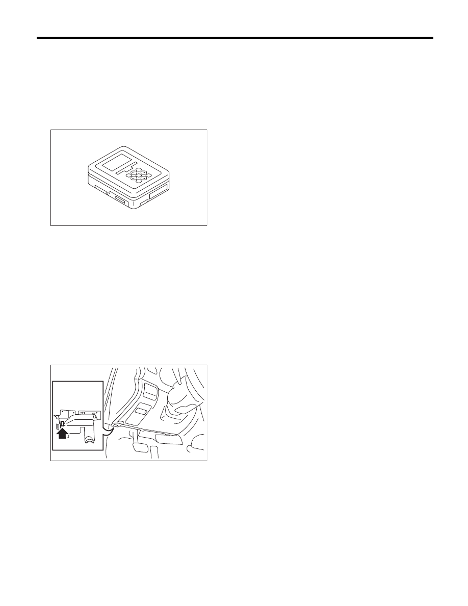
9. Subaru Select Monitor
A: OPERATION
1. HOW TO USE THE SUBARU SELECT
MONITOR
1) Prepare the Subaru Select Monitor kit. <Ref. to
EN(H4SO)(diag)-7, PREPARATION TOOL, Gen-
eral Description.>
2) Prepare PC with Subaru Select Monitor in-
stalled.
3) Connect the USB cable between SDI (Subaru
Diagnosis Interface) and USB port on the personal
computer (dedicated port for the Subaru Select
Monitor).
NOTE:
The dedicated port for the Subaru Select Monitor
means the USB port which was used to install the
Subaru Select Monitor.
4) Connect the diagnosis cable to SDI.
5) Connect SDI to data link connector located in the
lower portion of the instrument panel (on the driv-
er’s side).
CAUTION:
Do not connect the scan tools except for Suba-
ru Select Monitor and general scan tool.
6) Start the PC.
7) Turn the ignition switch to ON (engine OFF) and
run the “PC application for Subaru Select Monitor”.
8) Call up DTC and data, then record them.
NOTE:
For detailed operation procedures, refer to the “PC
application help for Subaru Select Monitor”.
EN-05692
EN-02533

EN(H4SO)(diag)-34
Subaru Select Monitor
ENGINE (DIAGNOSTICS)
2. READ CURRENT DATA FOR ENGINE (NORMAL MODE)
1) On the «Main Menu» display screen, select the {Each System Check}.
2) On the «System Selection Menu» display screen, select the {Engine Control System}.
3) Click the [OK] button after the information of engine type has been displayed.
4) On the «Engine Diagnosis» display screen, select the {Current Data Display & Save}.
5) On the «Current Data Display & Save» display screen, select the {Normal sampling}.
6) Using the scroll key, scroll the display screen up or down until the desired data is shown.
• A list of the support data is shown in the following table.
Contents
Display
Unit of measure
Note (at idling)
Engine load
Engine Load
%
21.0%
Engine coolant temperature signal
Coolant Temp.
°C or °F
85°C or 185°F or more
(after warm up)
A/F correction 1
A/F Correction #1
%
–0.8%
A/F learning 1
A/F Learning #1
%
0.0%
Intake manifold absolute pressure
Mani. Absolute Pressure
mmHg, kPa,
inHg or psig
200 — 300 mmHg,
26.7 — 40 kPa,
7.8 — 11.8 inHg or
3.8 — 5.8 psig
Engine speed signal
Engine Speed
rpm
700 rpm (Agree with the
tachometer indication)
Meter vehicle speed signal
Vehicle Speed
km/h or MPH
0 km/h or 0 MPH
(at parking)
Ignition timing signal
Ignition Timing
deg
14 — 16 deg
Intake air temperature signal
Intake Air Temp.
°C or °F
(Ambient air temperature)
Intake air amount
Mass Air Flow
g/s or lb/m
2.5 g/s or 0.33 lb/m
Throttle opening angle signal
Throttle Opening Angle
%
2.0%
Rear oxygen sensor voltage
Rear O2 Sensor
V
0.1 — 0.7 V
Battery voltage
Battery Voltage
V
12 — 14 V
Mass air flow voltage
Air Flow Sensor Voltage
V
1.26 V
Injection 1 pulse width
Fuel Injection #1 Pulse
ms
2.82 ms
Atmospheric pressure signal
Atmosphere Pressure
mmHg, kPa,
inHg or psig
(Atmospheric pressure)
Intake manifold relative pressure
Mani. Relative Pressure
mmHg, kPa,
inHg or psig
(Air intake absolute pres-
sure – Atmospheric
pressure)
Ignition timing learning value
Learned Ignition Timing
deg
0 deg
Acceleration opening angle signal
Accel. Opening Angle
%
0.0%
Fuel temperature signal
Fuel Temp.
°C or °F
+20°C or +68°F
Purge control solenoid duty ratio
CPC Valve Duty Ratio
%
0 — 3%
Number of EGR steps
No. of EGR steps
STEP
0 STEP
A/F sensor current value 1
A/F Sensor #1 Current
mA
–0.2 — 0.2 mA
A/F sensor resistance value 1
A/F Sensor #1 Resistance
:
32
:
A/F Sensor # 1
A/F Sensor #1
—
1.0
A/F correction 3
A/F Correction #3
%
0.3%
A/F learning 3
A/F Learning #3
%
0.00%
Throttle motor duty
Throttle Motor Duty
%
–15%
Throttle power supply voltage
Throttle Motor Voltage
V
(Battery voltage)
Sub throttle sensor voltage
Sub-Throttle Sensor
V
1.52 V
Main throttle sensor voltage
Main-Throttle Sensor
V
0.66 V
Sub accelerator sensor voltage
Sub-Accelerator Sensor
V
0.68 V
Main acceleration sensor voltage
Main-Accelerator Sensor
V
0.68 V
Memory vehicle speed
Memorized Cruise Speed
km/h or MPH
0 km/h or 0 MPH
Fuel level sensor signal
Fuel level resistance
:
2 — 96
:
Нет комментариевНе стесняйтесь поделиться с нами вашим ценным мнением.
Текст