Subaru Legacy IV (2008 year). Service manual — part 563

EN(H6DO)(diag)-225
Diagnostic Procedure with Diagnostic Trouble Code (DTC)
ENGINE (DIAGNOSTICS)
Step
Check
Yes
No
1
CHECK CONDITION OF CRANKSHAFT PO-
SITION SENSOR.
Is the crankshaft position sen-
sor installation bolt tightened
securely?
Go to step 2.
Tighten the crank-
shaft position sen-
sor installation bolt
securely.
2
CHECK CRANKSHAFT POSITION SENSOR.
1) Turn the ignition switch to OFF.
2) Remove the crankshaft position sensor.
3) Measure the resistance between connector
terminals of crankshaft position sensor.
Terminals
No. 1 — No. 2:
Is the resistance between 1 and
4 k
:?
Go to step 3.
Replace the crank-
shaft position sen-
sor. <Ref. to
FU(H6DO)-21,
Crankshaft Posi-
tion Sensor.>
3
CHECK HARNESS BETWEEN ECM AND
CRANK SHAFT POSITION SENSOR.
1) Disconnect the connectors from ECM.
2) Measure the resistance of harness between
ECM and crankshaft position sensor connector.
Connector & terminal
(B134) No. 13 — (E10) No. 1:
(B134) No. 14 — (E10) No. 2:
Is the resistance less than 1
:? Repair the poor
contact of ECM
and crankshaft
position sensor
connector.
Repair the harness
and connector.
NOTE:
In this case, repair
the following item:
• Open circuit in
harness between
ECM and crank-
shaft position sen-
sor connector
• Poor contact of
coupling connector
EN(H6DO)(diag)-226
Diagnostic Procedure with Diagnostic Trouble Code (DTC)
ENGINE (DIAGNOSTICS)
BY:DTC P0336 CRANKSHAFT POSITION SENSOR “A” CIRCUIT RANGE/
PERFORMANCE
DTC DETECTING CONDITION:
• Two consecutive driving cycles with fault
• GENERAL DESCRIPTION <Ref. to GD(H6DO)-99, DTC P0336 CRANKSHAFT POSITION SENSOR “A”
CIRCUIT RANGE/PERFORMANCE, Diagnostic Trouble Code (DTC) Detecting Criteria.>
TROUBLE SYMPTOM:
• Engine stalls.
• Failure of engine to start
CAUTION:
After repair or replacement of faulty parts, perform Clear Memory Mode <Ref. to EN(H6DO)(diag)-52,
OPERATION, Clear Memory Mode.>, and Inspection Mode <Ref. to EN(H6DO)(diag)-44, PROCEDURE,
Inspection Mode.>.
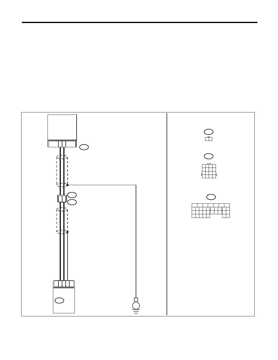
WIRING DIAGRAM:
EN-03926
5
6
7
8
2
1
9
4
3
10
24
22 23
25
11 12 13 14 15
26 27
28
16 17
18 19 20 21
33 34
29
32
30 31
1
2
8
7
14
24
B20
E1
E10
E10
1 2
B134
ECM
CRANKSHAFT
POSITION
SENSOR
13
E
B20
B134
1 2 3 4
5 6 7 8
9 10 11 12
13 14 15 16

EN(H6DO)(diag)-227
Diagnostic Procedure with Diagnostic Trouble Code (DTC)
ENGINE (DIAGNOSTICS)
Step
Check
Yes
No
1
CHECK CONDITION OF CRANKSHAFT PO-
SITION SENSOR.
Turn the ignition switch to OFF.
Is the crankshaft position sen-
sor installation bolt tightened
securely?
Go to step 2.
Tighten the crank-
shaft position sen-
sor installation bolt
securely.
2
CHECK CRANKSHAFT PLATE.
Are the crankshaft plate teeth
cracked or damaged?
Replace the crank-
shaft plate.
Go to step 3.
3
CHECK INSTALLATION CONDITION OF
TIMING CHAIN.
Turn the crankshaft, and align alignment mark
on crank sprocket with alignment mark on cylin-
der block.
ST
18252AA000
CRANKSHAFT
SOCKET
Is the timing chain dislocated
from its proper position?
Correct the instal-
lation condition of
timing chain. <Ref.
to ME(H6DO)-46,
Timing Chain
Assembly.>
Replace the crank-
shaft position sen-
sor. <Ref. to
FU(H6DO)-21,
Crankshaft Posi-
tion Sensor.>
EN(H6DO)(diag)-228
Diagnostic Procedure with Diagnostic Trouble Code (DTC)
ENGINE (DIAGNOSTICS)
BZ:DTC P0340 CAMSHAFT POSITION SENSOR “A” CIRCUIT (BANK 1 OR SINGLE
SENSOR)
DTC DETECTING CONDITION:
• Immediately at fault recognition
• GENERAL DESCRIPTION <Ref. to GD(H6DO)-101, DTC P0340 CAMSHAFT POSITION SENSOR “A”
CIRCUIT (BANK 1 OR SINGLE SENSOR), Diagnostic Trouble Code (DTC) Detecting Criteria.>
TROUBLE SYMPTOM:
• Engine stalls.
• Failure of engine to start
CAUTION:
After repair or replacement of faulty parts, perform Clear Memory Mode <Ref. to EN(H6DO)(diag)-52,
OPERATION, Clear Memory Mode.>, and Inspection Mode <Ref. to EN(H6DO)(diag)-44, PROCEDURE,
Inspection Mode.>.
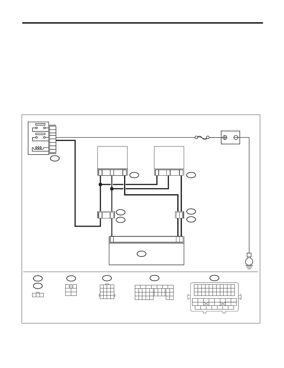
WIRING DIAGRAM:
EN-06876
5
6
7
8
2
1
9
4
3
10
24
22 23
25
11 12 13 14 15
26 27
28
16 17
18 19 20 21
33 34
29
32
30 31
B47
1
2
4
6
3
5
E
E2
B21
3
22
SBF-7
E74
E1
B20
E73
1
3
11
2
1
ECM
B134
1
3
4
1
2
5
6
B20
E74
B47
1 2 3
B134
E73
BATTERY
MAIN RELAY
2
21
1 2 3 4
5 6 7 8
9 10 11 12
13 14 15 16
2
6
48
B21
1 2 3 4 5 6 7 8 9 10 11
12 13 14 15 16 17 18 19 20 21 22
23 24 25 26 27 28 29 30 31 32 33
34
35
42
43
36
37
38
39
48
49
50
51
52
53
54
40
41
44
45
46
47
CAMSHAFT
POSITION
SENSOR LH
CAMSHAFT
POSITION
SENSOR RH
Нет комментариевНе стесняйтесь поделиться с нами вашим ценным мнением.
Текст