Subaru Legacy IV (2008 year). Service manual — part 597

GD(H6DO)-8
List of Diagnostic Trouble Code (DTC)
GENERAL DESCRIPTION
P1574
Key Communication Failure
<Ref. to GD(H6DO)-181, DTC P1574 KEY COMMUNICATION FAILURE,
Diagnostic Trouble Code (DTC) Detecting Criteria.>
P1576
EGI Control Module EEPROM
<Ref. to GD(H6DO)-181, DTC P1576 EGI CONTROL MODULE EEPROM,
Diagnostic Trouble Code (DTC) Detecting Criteria.>
P1577
IMM Control Module EEPROM
<Ref. to GD(H6DO)-181, DTC P1577 IMM CONTROL MODULE EEPROM,
Diagnostic Trouble Code (DTC) Detecting Criteria.>
P1578
Meter Failure
<Ref. to GD(H6DO)-181, DTC P1578 METER FAILURE, Diagnostic Trouble
Code (DTC) Detecting Criteria.>
P1602
Control Module Programming Error
<Ref. to GD(H6DO)-182, DTC P1602 CONTROL MODULE PROGRAM-
MING ERROR, Diagnostic Trouble Code (DTC) Detecting Criteria.>
P2088
Intake Camshaft Position Actuator
Control Circuit Low (Bank 1)
<Ref. to GD(H6DO)-184, DTC P2088 INTAKE CAMSHAFT POSITION
ACTUATOR CONTROL CIRCUIT LOW (BANK 1), Diagnostic Trouble Code
(DTC) Detecting Criteria.>
P2089
Intake Camshaft Position Actuator
Control Circuit High (Bank 1)
<Ref. to GD(H6DO)-185, DTC P2089 INTAKE CAMSHAFT POSITION
ACTUATOR CONTROL CIRCUIT HIGH (BANK 1), Diagnostic Trouble Code
(DTC) Detecting Criteria.>
P2092
Intake Camshaft Position Actuator
Control Circuit Low (Bank 2)
<Ref. to GD(H6DO)-186, DTC P2092 INTAKE CAMSHAFT POSITION
ACTUATOR CONTROL CIRCUIT LOW (BANK 2), Diagnostic Trouble Code
(DTC) Detecting Criteria.>
P2093
Intake Camshaft Position Actuator
Control Circuit High (Bank 2)
<Ref. to GD(H6DO)-186, DTC P2093 INTAKE CAMSHAFT POSITION
ACTUATOR CONTROL CIRCUIT HIGH (BANK 2), Diagnostic Trouble Code
(DTC) Detecting Criteria.>
P2096
Post Catalyst Fuel Trim System Too
Lean (Bank 1)
<Ref. to GD(H6DO)-187, DTC P2096 POST CATALYST FUEL TRIM SYS-
TEM TOO LEAN (BANK 1), Diagnostic Trouble Code (DTC) Detecting Crite-
ria.>
P2097
Post Catalyst Fuel Trim System Too
Rich (Bank 1)
<Ref. to GD(H6DO)-189, DTC P2097 POST CATALYST FUEL TRIM SYS-
TEM TOO RICH (BANK 1), Diagnostic Trouble Code (DTC) Detecting Crite-
ria.>
P2098
Post Catalyst Fuel Trim System Too
Lean Bank 2
<Ref. to GD(H6DO)-190, DTC P2098 POST CATALYST FUEL TRIM SYS-
TEM TOO LEAN BANK 2, Diagnostic Trouble Code (DTC) Detecting Crite-
ria.>
P2099
Post Catalyst Fuel Trim System Too
Rich Bank 2
<Ref. to GD(H6DO)-190, DTC P2099 POST CATALYST FUEL TRIM SYS-
TEM TOO RICH BANK 2, Diagnostic Trouble Code (DTC) Detecting Crite-
ria.>
P2101
Throttle Actuator Control Motor Circuit
Range/Performance
<Ref. to GD(H6DO)-191, DTC P2101 THROTTLE ACTUATOR CONTROL
MOTOR CIRCUIT RANGE/PERFORMANCE, Diagnostic Trouble Code
(DTC) Detecting Criteria.>
P2102
Throttle Actuator Control Motor Circuit
Low
<Ref. to GD(H6DO)-193, DTC P2102 THROTTLE ACTUATOR CONTROL
MOTOR CIRCUIT LOW, Diagnostic Trouble Code (DTC) Detecting Criteria.>
P2103
Throttle Actuator Control Motor Circuit
High
<Ref. to GD(H6DO)-195, DTC P2103 THROTTLE ACTUATOR CONTROL
MOTOR CIRCUIT HIGH, Diagnostic Trouble Code (DTC) Detecting Crite-
ria.>
P2109
Throttle/Pedal Position Sensor “A”
Minimum Stop Performance
<Ref. to GD(H6DO)-197, DTC P2109 THROTTLE/PEDAL POSITION SEN-
SOR “A” MINIMUM STOP PERFORMANCE, Diagnostic Trouble Code (DTC)
Detecting Criteria.>
P2122
Throttle/Pedal Position Sensor/Switch
“D” Circuit Low Input
<Ref. to GD(H6DO)-199, DTC P2122 THROTTLE/PEDAL POSITION SEN-
SOR/SWITCH “D” CIRCUIT LOW INPUT, Diagnostic Trouble Code (DTC)
Detecting Criteria.>
P2123
Throttle/Pedal Position Sensor/Switch
“D” Circuit High Input
<Ref. to GD(H6DO)-201, DTC P2123 THROTTLE/PEDAL POSITION SEN-
SOR/SWITCH “D” CIRCUIT HIGH INPUT, Diagnostic Trouble Code (DTC)
Detecting Criteria.>
P2127
Throttle/Pedal Position Sensor/Switch
“E” Circuit Low Input
<Ref. to GD(H6DO)-203, DTC P2127 THROTTLE/PEDAL POSITION SEN-
SOR/SWITCH “E” CIRCUIT LOW INPUT, Diagnostic Trouble Code (DTC)
Detecting Criteria.>
DTC
Item
Index

GD(H6DO)-9
List of Diagnostic Trouble Code (DTC)
GENERAL DESCRIPTION
P2128
Throttle/Pedal Position Sensor/
Switch “E” Circuit High Input
<Ref. to GD(H6DO)-205, DTC P2128 THROTTLE/PEDAL POSITION SEN-
SOR/SWITCH “E” CIRCUIT HIGH INPUT, Diagnostic Trouble Code (DTC)
Detecting Criteria.>
P2135
Throttle/Pedal Position Sensor/
Switch “A”/“B” Voltage Correlation
<Ref. to GD(H6DO)-207, DTC P2135 THROTTLE/PEDAL POSITION SEN-
SOR/SWITCH “A”/“B” VOLTAGE CORRELATION, Diagnostic Trouble Code
(DTC) Detecting Criteria.>
P2138
Throttle/Pedal Position Sensor/
Switch “D”/“E” Voltage Correlation
<Ref. to GD(H6DO)-209, DTC P2138 THROTTLE/PEDAL POSITION SEN-
SOR/SWITCH “D”/“E” VOLTAGE CORRELATION, Diagnostic Trouble Code
(DTC) Detecting Criteria.>
P2227
Barometric Pressure Circuit Range/
Performance
<Ref. to GD(H6DO)-211, DTC P2227 BAROMETRIC PRESSURE CIRCUIT
RANGE/PERFORMANCE, Diagnostic Trouble Code (DTC) Detecting Crite-
ria.>
P2228
Barometric Pressure Circuit Low
<Ref. to GD(H6DO)-212, DTC P2228 BAROMETRIC PRESSURE CIRCUIT
LOW, Diagnostic Trouble Code (DTC) Detecting Criteria.>
P2229
Barometric Pressure Circuit High
<Ref. to GD(H6DO)-213, DTC P2229 BAROMETRIC PRESSURE CIRCUIT
HIGH, Diagnostic Trouble Code (DTC) Detecting Criteria.>
DTC
Item
Index
GD(H6DO)-10
Diagnostic Trouble Code (DTC) Detecting Criteria
GENERAL DESCRIPTION
2. Diagnostic Trouble Code (DTC) Detecting Criteria
A: DTC P0011 INTAKE CAMSHAFT POSITION - TIMING OVER-ADVANCED OR
SYSTEM PERFORMANCE (BANK 1)
1. OUTLINE OF DIAGNOSIS
Detect the AVCS system malfunction.
Judge NG when the amount of AVCS actual timing advance does not approach to the amount of AVCS target
timing advance.
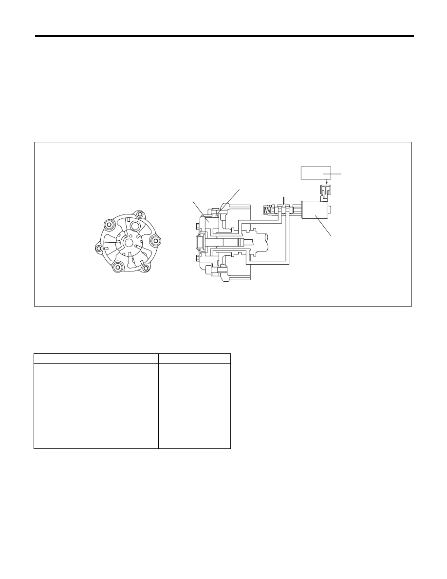
2. COMPONENT DESCRIPTION
3. ENABLE CONDITION
4. GENERAL DRIVING CYCLE
Perform the diagnosis continuously after warming up when the engine speed increases and AVCS operates.
(1)
AVCS timing controller
(3)
Engine control module (ECM)
(5)
Oil pressure
(2)
Vane
(4)
Oil flow control solenoid valve
Secondary Parameters
Enable Conditions
Time of establishing all secondary
parameter conditions
t 3000 ms
Battery voltage
t 10.9 V
Engine speed
t 1500 rpm
Engine coolant temperature
t 50 °C (122 °F)
AVCS control
Operation
Target advance angle
t 0 °CA
Target timing advance change amount
(per 64 ms)
< 1.07 °CA
EN-01852
(3)
(4)
(1)
(5)
(2)

GD(H6DO)-11
Diagnostic Trouble Code (DTC) Detecting Criteria
GENERAL DESCRIPTION
5. DIAGNOSTIC METHOD
1) When the conditions during which the differences of AVCS target timing advance amount and AVCS ac-
tual timing advance amount is large continues for certain amount of time.
2) When the differences of target timing advance amount and actual timing advance amount is calculated
during AVCS control, and the difference per predetermined time is the specified value or larger.
• Abnormality Judgement
Judge as NG when the following conditions are established within the predetermined time.
Time Needed for Diagnosis: 30000 ms
Malfunction Indicator Light Illumination: Illuminates when malfunction occurs in 2 continuous driving cy-
cles.
• Normality Judgement
Judge as OK and clear the NG if the following conditions are established within the predetermined time.
Time Needed for Diagnosis: 30000 ms
Judgement Value
Malfunction criteria
Threshold value
6(Target position – Actual position)
> 8000 °CA (Bank 1)
> 8000 °CA (Bank 2)
or
6(Target position – Actual position)
< –2500 °CA (Bank 1)
< –2500 °CA (Bank 2)
Judgement Value
Malfunction criteria
Threshold value
6(Target position – Actual position)
d 8000 °CA (Bank 1)
d 8000 °CA (Bank 2)
and
t –2500 °CA (Bank 1)
t –2500 °CA (Bank 2)
Нет комментариевНе стесняйтесь поделиться с нами вашим ценным мнением.
Текст