Subaru Legacy IV (2008 year). Service manual — part 862

TPM(diag)-34
Diagnostic Procedure with Diagnostic Trouble Code (DTC)
TIRE PRESSURE MONITORING SYSTEM (DIAGNOSTICS)
P: DTC 44 TRANSMITTER 4 FUNCTION CODE ABNORMAL
DTC DETECTING CONDITION:
Unexpected function codes received from each transmitter.
TROUBLE SYMPTOM:
Tire pressure warning light blinks 25 times and then illuminates.
Step
Check
Yes
No
1
START FL TRANSMITTER.
1) Connect the Subaru Select Monitor and
then turn the ignition switch to ON.
2) Select “Transmit ID Monitor”. <Ref. to
TPM(diag)-10, DISPLAY TRANSMITTER (ID).,
OPERATION, Subaru Select Monitor.>
3) Use the transmitter registration tool and
transmit the ID from the FL transmitter to check
“Latest reception ID”.
Is “Latest reception ID”
updated?
Go to step 2.
Replace front left
transmitter.
2
CHECK FL TRANSMITTER ID.
Check the ID displayed in the updated ID dis-
play and the tire 1 registered ID.
Are the two IDs same?
Go to step 3.
Record the
received ID update
as the FL transmit-
ter. Go to step 3.
3
START FR TRANSMITTER.
Use the transmitter registration tool and trans-
mit the ID from the FR transmitter to check “Lat-
est reception ID”.
Is “Latest reception ID”
updated?
Go to step 4.
Replace the front
right transmitter.
4
CHECK FR TRANSMITTER ID.
Check the ID displayed in the updated ID dis-
play and the tire 2 registered ID.
Are the two IDs same?
Go to step 5.
Record the
received ID update
as the FR transmit-
ter. Go to step 5.
5
START RR TRANSMITTER.
Use the transmitter registration tool and trans-
mit the ID from the RR transmitter to check “Lat-
est reception ID”.
Is “Latest reception ID”
updated?
Go to step 6.
Replace the RR
transmitter.
6
CHECK RR TRANSMITTER ID.
Check the ID displayed in the updated ID dis-
play and the tire 3 registered ID.
Are the two IDs same?
Go to step 7.
Record the
received ID update
as the RR transmit-
ter. Go to step 7.
7
START RL TRANSMITTER.
Use the transmitter registration tool and trans-
mit the ID from the RL transmitter to check “Lat-
est reception ID”.
Is “Latest reception ID”
updated?
Go to step 8.
Replace the RL
transmitter.
8
CHECK RL TRANSMITTER ID.
Check the ID displayed in the updated ID dis-
play and the tire 4 registered ID.
Are the two IDs same?
Go to step 9.
Record the
received ID update
as the RL transmit-
ter. Go to step 9.
9
CHECK MALFUNCTION TRANSMITTER.
Is ID recorded by this proce-
dure?
Go to step 10.
Replace the trans-
mitter indicated by
DTC.
10
CHECK MALFUNCTION TRANSMITTER.
Check the registered ID of the transmitter indi-
cated by DTC.
Is there checked ID in the
record?
Replace the trans-
mitter of the
recorded position.
Replace the trans-
mitter indicated by
DTC.

TPM(diag)-35
Diagnostic Procedure with Diagnostic Trouble Code (DTC)
TIRE PRESSURE MONITORING SYSTEM (DIAGNOSTICS)
Q: DTC 51 TRANSMITTER 1 BATTERY VOLTAGE DECREASE
NOTE:
Refer to DTC 54 for diagnostic procedure. <Ref. to TPM(diag)-35, DTC 54 TRANSMITTER 4 BATTERY
VOLTAGE DECREASE, Diagnostic Procedure with Diagnostic Trouble Code (DTC).>
R: DTC 52 TRANSMITTER 2 BATTERY VOLTAGE DECREASE
NOTE:
Refer to DTC 54 for diagnostic procedure. <Ref. to TPM(diag)-35, DTC 54 TRANSMITTER 4 BATTERY
VOLTAGE DECREASE, Diagnostic Procedure with Diagnostic Trouble Code (DTC).>
S: DTC 53 TRANSMITTER 3 BATTERY VOLTAGE DECREASE
NOTE:
Refer to DTC 54 for diagnostic procedure. <Ref. to TPM(diag)-35, DTC 54 TRANSMITTER 4 BATTERY
VOLTAGE DECREASE, Diagnostic Procedure with Diagnostic Trouble Code (DTC).>
T: DTC 54 TRANSMITTER 4 BATTERY VOLTAGE DECREASE
DTC DETECTING CONDITION:
Low battery signals received 20 times from each transmitter.
TROUBLE SYMPTOM:
Tire pressure warning light blinks 25 times and then illuminates.
Step
Check
Yes
No
1
CHECK TRANSMITTER.
1) Replace all transmitters with new parts and
register their IDs. <Ref. to TPM(diag)-10, REG-
ISTER TRANSMITTER ID, OPERATION, Sub-
aru Select Monitor.>
2) Perform the Clear Memory Mode, and per-
form driving test.
Is the fault eliminated?
Internal battery of
the transmitter had
worn out.
Replace the tire
pressure monitor-
ing control module.
<Ref. to WT-11,
TIRE PRESSURE
MONITORING
CONTROL MOD-
ULE, REMOVAL,
Tire Pressure
Monitoring Sys-
tem.>
TPM(diag)-36
Diagnostic Procedure with Diagnostic Trouble Code (DTC)
TIRE PRESSURE MONITORING SYSTEM (DIAGNOSTICS)
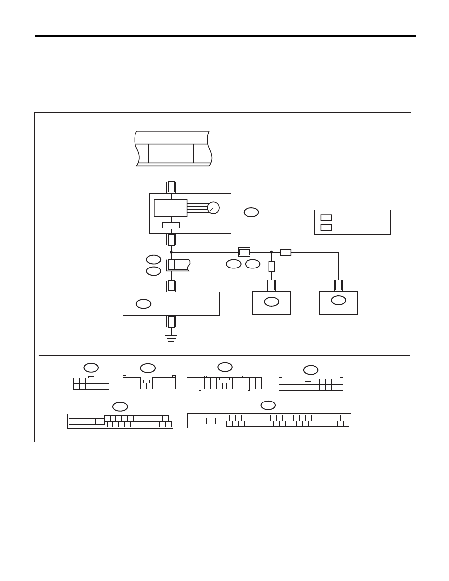
U: DTC 61 VEHICLE SPEED IS ABNORMAL
DTC DETECTING CONDITION:
Vehicle speed function codes were received from the transmitter, but the vehicle speed signal was not input
to the module.
TROUBLE SYMPTOM:
Tire pressure warning light blinks 25 times and then illuminates.
WIRING DIAGRAM:
4
A:
i10
A1
A19
i102
R167
R211
I/F
12
9
i102
1 2 3
8 9 10
4
11 12 13 14 15 16
5 6 7
A:
i10
1 2 3 4 5
6 7 8 9 10
11 12
19 20 21
13 14 15 16
17 18
22
R211
18
B301
B310
FB-17
F/B FUSE NO. 7
(B)
i3
B38
B301
4 5 6 7 8 9
16 17 18 19 20
2 3
1
21 22 23 24 25 26
10 11
13
14
12
15
B310
B38
1 2 3 4
5 6 7 8 9
10 11 12 13 14 15 16 17 18 19 20
23
33
1 2 3 4 5 6
7 8 9 10 11 12
ABS
VDC
ABS
VDC
12
14 15 16 17 18 19 20 21
22
23
24
25
26 27 28 29 30 31 32 33 34 35 36 37 38 39 40 41 42
13
4 5 6 7 8 9
2 3
1
10 11
43 44 45 46
TPM00027
TO POWER SUPPLY CIRCUIT
MICRO
COMPUTER
SPEEDOMETER
COMBINATION
METER
: MODEL WITH VDC
: MODEL WITHOUT VDC
ABS
CONTROL MODULE
VDC
CONTROL MODULE
TPM CONTROL MODULE

TPM(diag)-37
Diagnostic Procedure with Diagnostic Trouble Code (DTC)
TIRE PRESSURE MONITORING SYSTEM (DIAGNOSTICS)
Step
Check
Yes
No
1
CHECK TIRE PRESSURE MONITORING
CONTROL MODULE.
1) Connect an oscilloscope to the terminal No.
4 of the tire pressure monitoring control module
connector (R211).
2) Drive the vehicle at 40 km/h (25 MPH) and
check the vehicle speed signal at that time.
Is the vehicle speed being
input?
Replace the tire
pressure monitor-
ing control module.
<Ref. to WT-11,
TIRE PRESSURE
MONITORING
CONTROL MOD-
ULE, REMOVAL,
Tire Pressure
Monitoring Sys-
tem.>
Go to step 2.
2
CHECK HARNESS.
1) Disconnect the combination meter connec-
tor (i10).
2) Connect the tire pressure monitoring control
module connector (R211) and combination
meter connector (i10) and measure the resis-
tance.
Is the resistance less than 0.5
:? Check the combi-
nation meter. <Ref.
to IDI-22,
REMOVAL, Com-
bination Meter.>
Repair or replace
the open circuit of
the harness.
Нет комментариевНе стесняйтесь поделиться с нами вашим ценным мнением.
Текст