Subaru Legacy IV (2008 year). Service manual — part 577
EN(H6DO)(diag)-281
Diagnostic Procedure with Diagnostic Trouble Code (DTC)
ENGINE (DIAGNOSTICS)
DG:DTC P1400 FUEL TANK PRESSURE CONTROL SOLENOID VALVE CIRCUIT
LOW
DTC DETECTING CONDITION:
• Two consecutive driving cycles with fault
• GENERAL DESCRIPTION <Ref. to GD(H6DO)-169, DTC P1400 FUEL TANK PRESSURE CONTROL
SOLENOID VALVE CIRCUIT LOW, Diagnostic Trouble Code (DTC) Detecting Criteria.>
CAUTION:
After repair or replacement of faulty parts, perform Clear Memory Mode <Ref. to EN(H6DO)(diag)-52,
OPERATION, Clear Memory Mode.>, and Inspection Mode <Ref. to EN(H6DO)(diag)-44, PROCEDURE,
Inspection Mode.>.
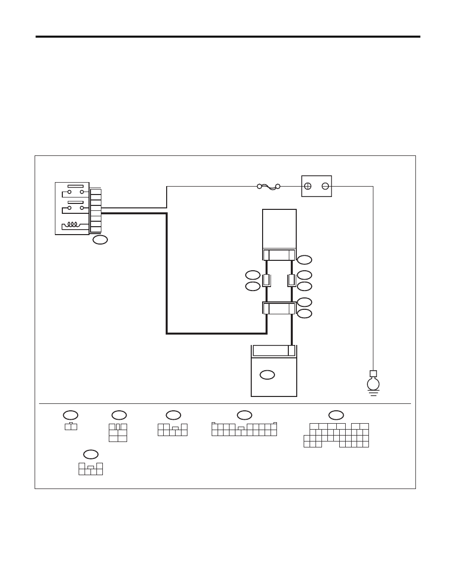
WIRING DIAGRAM:
SBF-7
R68
B47
R67
B97
R213
1 2
3
4
1
2
5
6
R68
R213
R15
R67
R46
R1
B97
B47
E
28
5
3
6
4
2
1
1
2
7
15
6
5
B136
B136
ECM
MAIN RELAY
PRESSURE
CONTROL
SOLENOID
VALVE
BATTERY
1
2
3 4 5 6
1 2 3 4
5 6 7 8 9
10 11 12 13 14 15 16 17 18 19 20
1 2
3
4 5 6 7 8
16
10 11 12 13 14 15
25
24
30
9
8
7
17 18 19 20
28
21 22 23
29
32
31
1
2
3
4
5
6
27
26
33 34 35
EN-05238

EN(H6DO)(diag)-282
Diagnostic Procedure with Diagnostic Trouble Code (DTC)
ENGINE (DIAGNOSTICS)
Step
Check
Yes
No
1
CHECK OUTPUT SIGNAL OF ECM.
1) Turn the ignition switch to ON.
2) Measure the voltage between ECM and
chassis ground.
Connector & terminal
(B136) No. 28 (+) — Chassis ground (–):
Is the voltage 10 V or more?
Repair the poor
contact of ECM
connector.
Go to step 2.
2
CHECK HARNESS BETWEEN ECM AND
PRESSURE CONTROL SOLENOID VALVE.
1) Turn the ignition switch to OFF.
2) Disconnect the connector from the ECM
and pressure control solenoid valve.
3) Measure the resistance between pressure
control solenoid valve and chassis ground.
Connector & terminal
(R68) No. 2 — Chassis ground:
Is the resistance 1 M
: or
more?
Go to step 3.
Repair the ground
short circuit of har-
ness between
ECM and pressure
control solenoid
valve connector.
3
CHECK HARNESS BETWEEN ECM AND
PRESSURE CONTROL SOLENOID VALVE.
Measure the resistance of harness between
ECM and pressure control solenoid valve con-
nector.
Connector & terminal
(B136) No. 28 — (R68) No. 2:
Is the resistance less than 1
:? Go to step 4.
Repair the harness
and connector.
NOTE:
In this case, repair
the following item:
• Open circuit in
harness between
ECM and pressure
control solenoid
valve connector
• Poor contact of
coupling connector
4
CHECK PRESSURE CONTROL SOLENOID
VALVE.
Measure the resistance between pressure con-
trol solenoid valve terminals.
Terminals
No. 1 — No. 2:
Is the resistance between 10 —
100
:?
Go to step 5.
Replace the pres-
sure control sole-
noid valve. <Ref. to
EC(H6DO)-13,
Pressure Control
Solenoid Valve.>
5
CHECK POWER SUPPLY TO THE PRES-
SURE CONTROL SOLENOID VALVE.
1) Turn the ignition switch to ON.
2) Measure the voltage between pressure con-
trol solenoid valve and chassis ground.
Connector & terminal
(R68) No. 1 (+) — Chassis ground (–):
Is the voltage 10 V or more?
Repair the poor
contact of pressure
control solenoid
valve connector.
Repair the harness
and connector.
NOTE:
In this case, repair
the following item:
• Open circuit in
harness between
main relay and
pressure control
solenoid valve
connector
• Poor contact of
coupling connector
• Poor contact of
main relay connec-
tor
EN(H6DO)(diag)-283
Diagnostic Procedure with Diagnostic Trouble Code (DTC)
ENGINE (DIAGNOSTICS)
DH:DTC P1420 FUEL TANK PRESSURE CONTROL SOL. VALVE CIRCUIT HIGH
DTC DETECTING CONDITION:
• Two consecutive driving cycles with fault
• GENERAL DESCRIPTION <Ref. to GD(H6DO)-171, DTC P1420 FUEL TANK PRESSURE CONTROL
SOL. VALVE CIRCUIT HIGH, Diagnostic Trouble Code (DTC) Detecting Criteria.>
CAUTION:
After repair or replacement of faulty parts, perform Clear Memory Mode <Ref. to EN(H6DO)(diag)-52,
OPERATION, Clear Memory Mode.>, and Inspection Mode <Ref. to EN(H6DO)(diag)-44, PROCEDURE,
Inspection Mode.>.
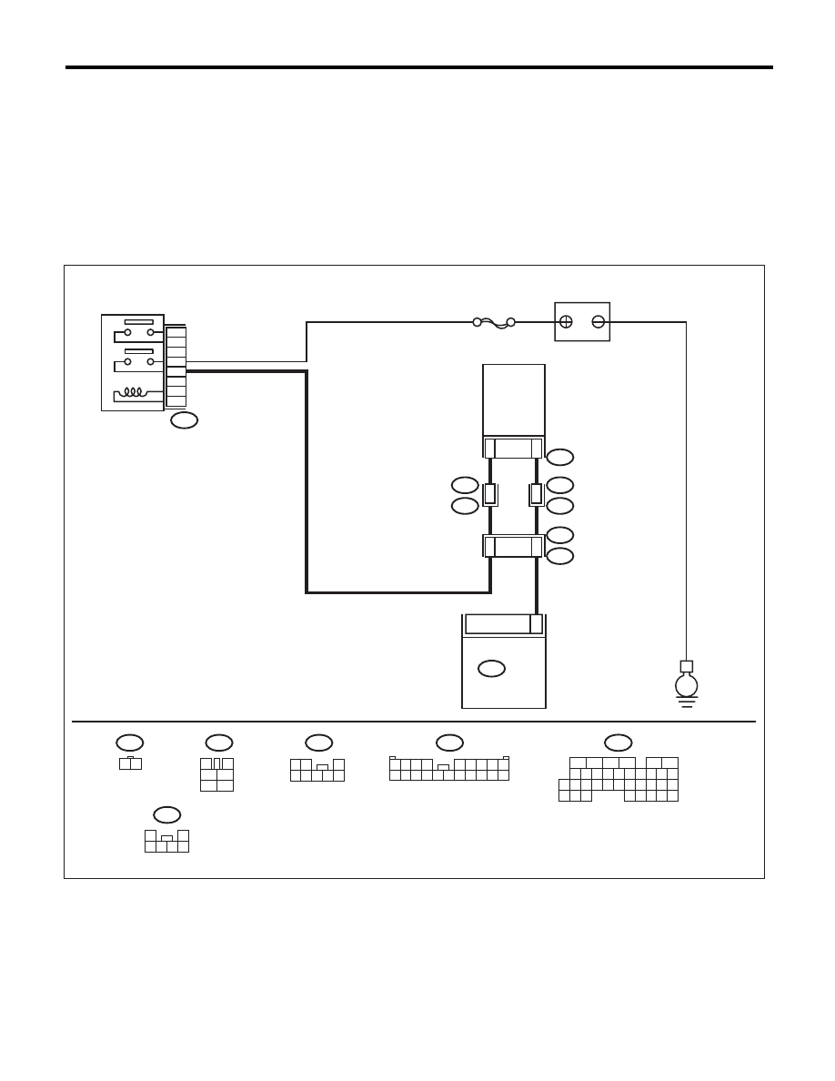
WIRING DIAGRAM:
SBF-7
R68
B47
R67
B97
R213
1 2
3
4
1
2
5
6
R68
R213
R15
R67
R46
R1
B97
B47
E
28
5
3
6
4
2
1
1
2
7
15
6
5
B136
B136
ECM
MAIN RELAY
PRESSURE
CONTROL
SOLENOID
VALVE
BATTERY
1
2
3 4 5 6
1 2 3 4
5 6 7 8 9
10 11 12 13 14 15 16 17 18 19 20
1 2
3
4 5 6 7 8
16
10 11 12 13 14 15
25
24
30
9
8
7
17 18 19 20
28
21 22 23
29
32
31
1
2
3
4
5
6
27
26
33 34 35
EN-05238
EN(H6DO)(diag)-284
Diagnostic Procedure with Diagnostic Trouble Code (DTC)
ENGINE (DIAGNOSTICS)
Step
Check
Yes
No
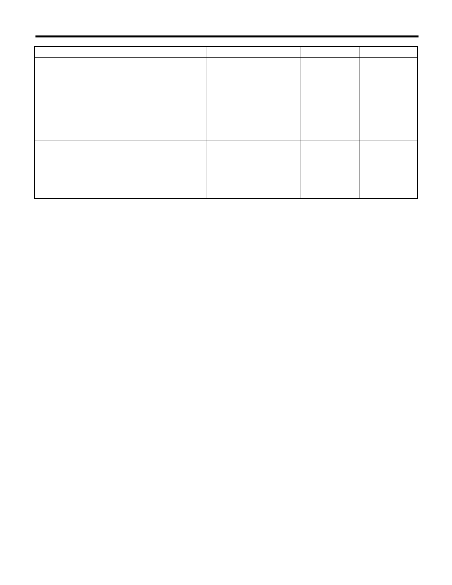
1
CHECK HARNESS BETWEEN ECM AND
PRESSURE CONTROL SOLENOID VALVE.
1) Turn the ignition switch to OFF.
2) Disconnect the connector from the ECM
and pressure control solenoid valve.
3) Turn the ignition switch to ON.
4) Measure the voltage between ECM and
chassis ground.
Connector & terminal
(B136) No. 28 (+) — Chassis ground (–):
Is the voltage 10 V or more?
Repair the short
circuit to power
supply in the har-
ness between the
ECM and pressure
control solenoid
valve connector.
Go to step 2.
2
CHECK PRESSURE CONTROL SOLENOID
VALVE.
1) Turn the ignition switch to OFF.
2) Measure the resistance between pressure
control solenoid valve terminals.
Terminals
No. 1 — No. 2:
Is the resistance less than 1
:? Replace the pres-
sure control sole-
noid valve. <Ref. to
EC(H6DO)-13,
Pressure Control
Solenoid Valve.>
Repair the poor
contact of ECM
connector.
Нет комментариевНе стесняйтесь поделиться с нами вашим ценным мнением.
Текст