Subaru Legacy IV (2008 year). Service manual — part 707
4AT(diag)-49
Diagnostic Procedure with Diagnostic Trouble Code (DTC)
AUTOMATIC TRANSMISSION (DIAGNOSTICS)
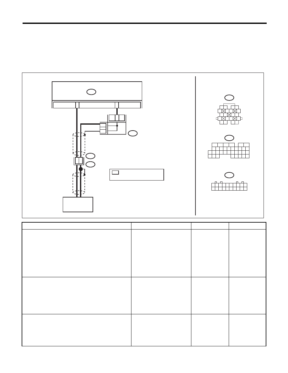
F: DTC P0720 OUTPUT SPEED SENSOR CIRCUIT
DTC DETECTING CONDITION:
• The vehicle speed signal is abnormal.
• The harness connector between TCM and front vehicle speed sensor is shorted or open.
TROUBLE SYMPTOM:
Driving performance is poor.
WIRING DIAGRAM:
Step
Check
Yes
No
1
CHECK HARNESS CONNECTOR BETWEEN
TCM AND TRANSMISSION.
1) Turn the ignition switch to OFF.
2) Disconnect the connectors from TCM and
transmission.
3) Measure the resistance of harness between
TCM connector and transmission connector.
Connector & terminal
(B54) No. 27 — (B11) No. 14:
Is the resistance less than 1
:? Go to step 2.
Repair the open
circuit of harness
between TCM and
transmission con-
nector.
2
CHECK HARNESS CONNECTOR BETWEEN
TCM AND TRANSMISSION.
Measure the resistance of harness between
TCM connector and transmission connector.
Connector & terminal
(B54) No. 16 — (B11) No. 18:
Is the resistance less than 1
:? Go to step 3.
Repair the open
circuit of harness
between TCM and
transmission con-
nector, and poor
contact of the con-
nector.
3
CHECK HARNESS CONNECTOR BETWEEN
TCM AND TRANSMISSION.
Measure the resistance of harness between
TCM connector and transmission connector.
Connector & terminal
(B54) No. 27 — Chassis ground:
Is the resistance 1 M
: or
more?
Go to step 4.
Repair the short
circuit of harness
between TCM and
transmission con-
nector.
AT-04332
18
14
B11
T4
27
B11
TCM
B54
B53
16
B53
*
*
*
B54
*
1 2
5
6 7
8
13
14 15
16
9 10
11 12
3 4
17 18
19 20
9
8
7
6
5
4
3
2
1
10
11 12 13 14 15 16 17 18 19 20
16
10 11 12 13 14 15
25
24
30
9
8
7
17 18 19 20
28
21 22 23
29
32
31
1
2
3
4
5
6
27
26
33 34 35
JOINT
CONNECTOR
: TERMINAL No. OPTIONAL
ARRANGEMENT
AMONG 1, 11 AND 12
FRONT VEHICLE
SPEED SENSOR

4AT(diag)-50
Diagnostic Procedure with Diagnostic Trouble Code (DTC)
AUTOMATIC TRANSMISSION (DIAGNOSTICS)
4
CHECK HARNESS CONNECTOR BETWEEN
TCM AND TRANSMISSION.
Measure the resistance of harness between
TCM connector and transmission connector.
Connector & terminal
(B54) No. 16 — Chassis ground:
Is the resistance 1 M
: or
more?
Go to step 5.
Repair the short
circuit of the har-
ness between
TCM and transmis-
sion connector,
and poor contact of
connector.
5
CHECK FRONT VEHICLE SPEED SENSOR.
Measure the resistance between transmission
connector receptacle’s terminals.
Connector & terminal
(T4) No. 14 — No. 18:
Is the resistance 450 — 650
:? Go to step 6.
Replace the front
vehicle speed sen-
sor. <Ref. to 4AT-
49, Front Vehicle
Speed Sensor.>
6
CHECK INPUT SIGNAL FOR TCM USING
SUBARU SELECT MONITOR.
1) Connect all connectors.
2) Connect the Subaru Select Monitor to data
link connector.
3) Lift up the vehicle.
4) Turn the ignition switch to ON and run the
Subaru Select Monitor.
5) Start the engine.
6) Read the data of “Front Wheel Speed” using
Subaru Select Monitor.
• Compare the speedometer with Subaru
Select Monitor indications.
• Vehicle speed is indicated in “km/h” or “MPH”
7) Slowly increase the vehicle speed to 60 km/
h (37 MPH).
NOTE:
The speed difference between front and rear
wheels may illuminate the ABS warning light,
but this does not indicate a malfunction. When
AT control diagnosis is finished, perform the
ABS or VDC clear memory of on-board diag-
nostics system. <Ref. to ABS(diag)-20, Clear
Memory Mode.> <Ref. to VDC(diag)-23, Clear
Memory Mode.>
Does the speedometer indica-
tion increase as the Subaru
Select Monitor front wheel
speed data increases?
Even if the ATF
temperature warn-
ing light blinks, the
circuit is in normal
condition at this
time. A temporary
poor contact of
connector or har-
ness may be the
cause. Repair the
harness in of front
vehicle speed sen-
sor circuit.
Go to step 7.
7
CHECK POOR CONTACT.
Is there poor contact in front
vehicle speed sensor circuit?
Repair the poor
contact.
Replace the TCM.
<Ref. to 4AT-61,
Transmission Con-
trol Module
(TCM).>
Step
Check
Yes
No
4AT(diag)-51
Diagnostic Procedure with Diagnostic Trouble Code (DTC)
AUTOMATIC TRANSMISSION (DIAGNOSTICS)
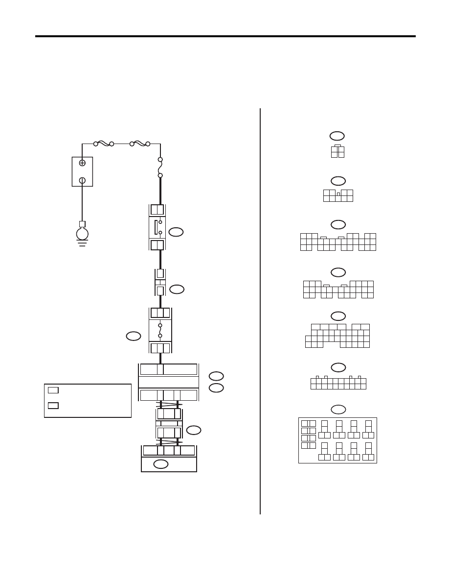
G: DTC P0724 BRAKE SWITCH CIRCUIT HIGH
DTC DETECTING CONDITION:
Brake switch malfunction, open input signal circuit
TROUBLE SYMPTOM:
Gear is not shifted down when driving a down hill.
WIRING DIAGRAM:
1
*
2
*
B159
2
1
3 4
8 9
7
6
5
B280
B281
C:
B:
B159
B280
B:
B281
C:
C23
B20
B30
3
5
9
M
AIN SBF
SBF-2
N
o
.8
E
18
17
TCM
B54
B365
2
4
3
B65
1
2
3
4
B65
B365
9
8
7
6
5
4
3
2
1
10
11 12 13 14 15 16 17 18 19
B225
1
*
2
*
1
*
2
*
7.5A
B54
B225
13
14
15 16
17
27
24
25
26
20
21
22
23
29
30
31
28
32
35
33
34
37
38
39
36
40
8
9
10
11 12
1
2
5
3
4
7
6
19
18
CAN JOINT
CONNECTOR
20
5
4
6 7
8
2
1
9
3
10
22
23
11 12 13 14 15
24 25
26 27
16 17 18
28 29
19 20
21
30
5 6 7
8
2
1
9
4
3
10
24
22 23
25
11 12 13 14 15
26
27 28
16 17 18 19
20 21
16
10 11 12 13 14 15
25
24
30
9
8
7
17 18 19 20
28
21 22 23
29
32
31
1
2
3
4
5
6
27
26
33 34 35
AT-04331
: TERMINAL No. OPTIONAL
ARRANGEMENT
AMONG 1, 2, 3, 11, 12 AND 13
: TERMINAL No. OPTIONAL
ARRANGEMENT
AMONG 8, 9, 10, 18, 19 AND 20
BODY INTEGRATED UNIT
FUSE & RELAY
BOX (F/B)
FUSE
(RELAY BLOCK)
B
A
TTER
Y
STOP LIGHT
SWITCH
(BLACK)

4AT(diag)-52
Diagnostic Procedure with Diagnostic Trouble Code (DTC)
AUTOMATIC TRANSMISSION (DIAGNOSTICS)
Step
Check
Yes
No
1
CHECK DTC.
Is DTC of CAN communication
displayed?
Perform the diag-
nosis according to
DTC.
Go to step 2.
2
CHECK BODY INTEGRATED UNIT.
1) Turn the ignition switch to OFF.
2) Connect the Subaru Select Monitor to data
link connector.
3) Turn the ignition switch to ON. (engine OFF)
4) Run the Subaru Select Monitor.
5) Read the data of “Stop Light Switch” using
Subaru Select Monitor. <Ref. to LAN(diag)-12,
OPERATION, Subaru Select Monitor.>
Is OFF displayed?
Go to step 3.
Go to step 4.
3
CHECK TCM.
Read the data of “Stop Light Switch” using Sub-
aru Select Monitor. <Ref. to 4AT(diag)-16,
OPERATION, Subaru Select Monitor.>
Is OFF displayed?
A temporary poor
contact of connec-
tor or harness may
be the cause.
Check the poor
contact.
Replace the TCM.
<Ref. to 4AT-61,
Transmission Con-
trol Module
(TCM).>
4
CHECK BODY INTEGRATED UNIT INPUT
SIGNAL.
1) Disconnect the harness connector of body
integrated unit.
2) Measure the voltage of harness between
body integrated unit and stop light switch.
Connector & terminal
(B281) No. 23 (+) — Chassis ground (–):
Is the voltage 10 V or more?
Go to step 5.
Go to step 7.
5
CHECK STOP LIGHT SWITCH.
1) Turn the ignition switch to OFF.
2) Disconnect the connector from stop light
switch.
3) Measure the resistance of harness between
stop light switch connectors.
Terminals
No. 2 — No. 3:
Is the resistance 1 M
: or
more?
Go to step 6.
Replace the stop
light switch.
6
CHECK HARNESS CONNECTOR BETWEEN
BODY INTEGRATED UNIT AND STOP LIGHT
SWITCH.
1) Turn the ignition switch to ON.
2) Measure the voltage of harness between
the body integrated unit and chassis ground.
Connector & terminal
(B281) No. 23 (+) — Chassis ground (–):
Is the voltage less than 1 V?
Go to step 7.
Repair the short
circuit of harness
between TCM and
stop light switch.
7
CHECK POOR CONTACT.
Is there poor contact in input
signal of brake switch?
Repair the poor
contact.
Check the body
integrated unit.
Нет комментариевНе стесняйтесь поделиться с нами вашим ценным мнением.
Текст