Subaru Legacy IV (2008 year). Service manual — part 1163
IM(diag)-9
Clear Memory Mode
IMMOBILIZER (DIAGNOSTICS)
7. Clear Memory Mode
A: OPERATION
1. ECM
1) On the «Main Menu» display, select the {Each
System Check}.
2) On the «System Selection Menu» display, select
the {Engine Control System}.
3) Select the [OK] after the information of engine
type is displayed.
4) On the «Engine Diagnosis» display, select the
{Clearing Memory}.
5) When “Done” is displayed on the display, end
the Subaru Select Monitor and turn the ignition
switch to OFF.
NOTE:
• After the memory is cleared, initial diagnosis of
the electronic throttle control is performed. Wait for
10 seconds or more after turning the ignition switch
to ON, and then start the engine.
• For detailed operation procedures, refer to the
“PC application help for Subaru Select Monitor”.
2. BODY INTEGRATED UNIT
1) On the «Main Menu» display, select the {Each
System Check}.
2) On the «System Selection Menu» display, select
the {Integ. Unit}.
3) After {Integ. Unit} is displayed, select [OK].
4) On the «Integ. unit mode failure diag» display,
select the {Clearing Memory}.
5) When “Done” is displayed on the display, end
the Subaru Select Monitor and turn the ignition
switch to OFF.
NOTE:
For detailed operation procedures, refer to the “PC
application help for Subaru Select Monitor”.
IM(diag)-10
Diagnostics Chart for Security Indicator Light
IMMOBILIZER (DIAGNOSTICS)
8. Diagnostics Chart for Security Indicator Light
A: INSPECTION
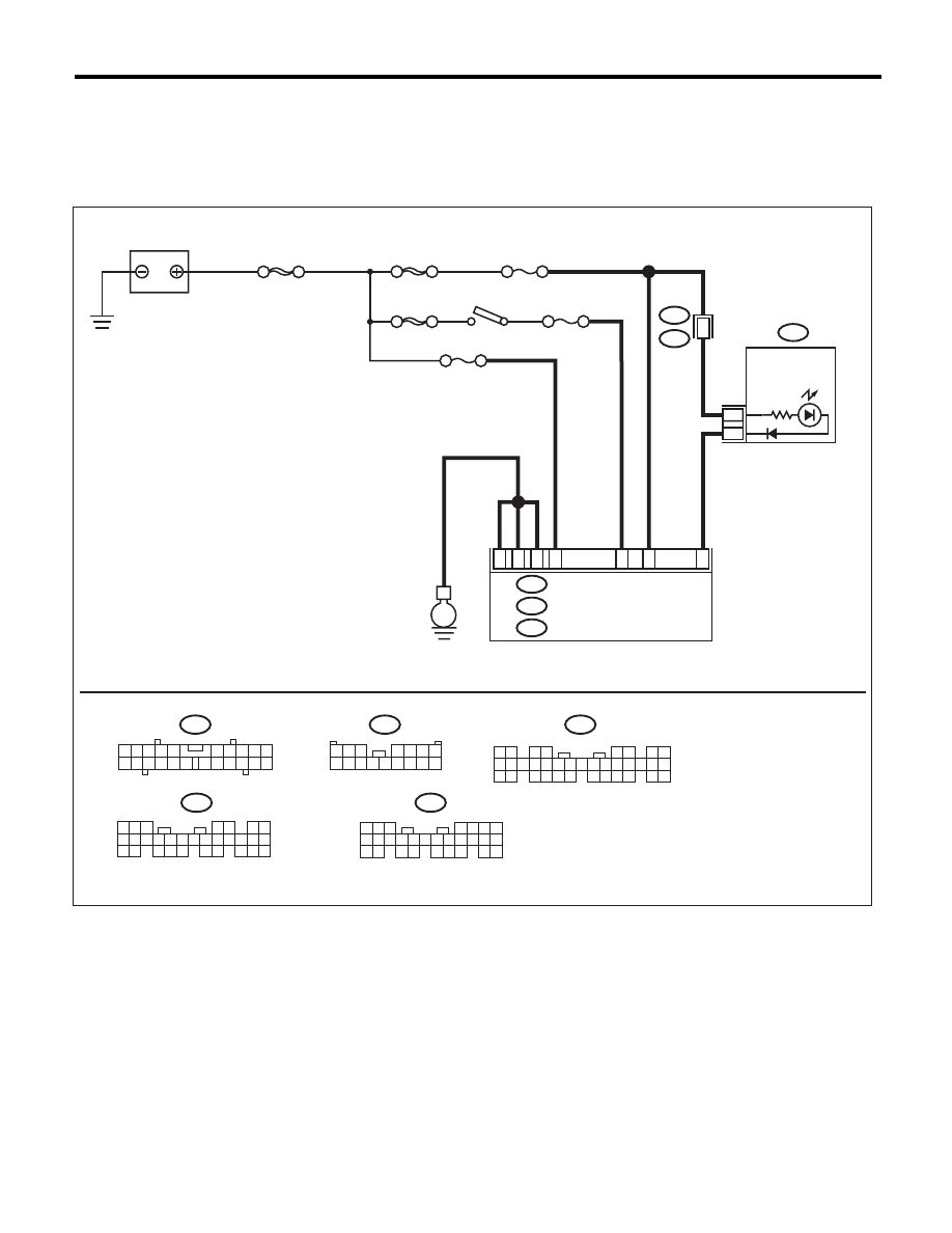
1. CHECK SECURITY INDICATOR LIGHT CIRCUIT
WIRING DIAGRAM:
MAIN SBF
SBF-3
BATTERY
COMBINATION METER
BODY INTEGRATED UNIT
i10
F/B No.7
F/B No.12
IGNITION
SWITCH
A33
C2
B7
C9
C8
A17
E
A:
A1
A1
M/B No.8
SBF-8
B22
i84
A:
B280
B:
B281
C:
5 6 7
8
2
1
9
4
3
10
24
22 23
25
11 12 13 14 15
26
27 28
16 17 18 19
20 21
B281
i84
1 2
3 4
5 6
7 8
9 10 11 12 13 14 15 16 17 18 19 20 21 22 23
24 25
26 27 28 29
30 31 32 33
34 35
5
4
6 7
8
2
1
9
3
10
22
23
11 12 13 14 15
24 25
26 27
16 17 18
28 29
19 20
21
30
B280
i10
2
1
3 4
6 7 8 9 10
22
21
20
19
18
17
16
15
14
13
12
11
5
A:
C:
B:
A:
10
R167
i102
i102
SECURITY
INDICATOR
LIGHT
1 2 3
4 5 6 7
8 9 10 11 12 13 14 15 16
IM-00203

IM(diag)-11
Diagnostics Chart for Security Indicator Light
IMMOBILIZER (DIAGNOSTICS)
Step
Check
Yes
No
1
CHECK SECURITY INDICATOR LIGHT.
1) Turn the ignition switch to OFF.
2) Disconnect the harness connector from
body integrated unit.
3) Connect a resistor (100
:) between the
body integrated unit harness connector termi-
nal (i84) No. 33 and chassis ground.
Does the security indicator light
illuminate?
Go to step 2.
Go to step 5.
2
CHECK BODY INTEGRATED UNIT GROUND
CIRCUIT.
Measure the resistance between body inte-
grated unit harness connector terminal and
chassis ground.
Connector & terminal
(B280) No. 22 — Chassis ground:
(B281) No. 8 — Chassis ground:
(B281) No. 9 — Chassis ground:
Is the resistance less than 10
:? Go to step 3.
Repair the open
circuit of body inte-
grated unit ground
circuit.
3
CHECK BODY INTEGRATED UNIT IGNITION
CIRCUIT.
1) Turn the ignition switch to ON. (engine OFF)
2) Measure the voltage between body inte-
grated unit harness connector terminal and
chassis ground.
Connector & terminal
(i84) No. 1 (+) — Chassis ground (–):
Is the voltage 10 V or more?
Go to step 4.
Check the harness
for open or short
circuit between the
body integrated
unit and ignition
switch.
4
CHECK BODY INTEGRATED UNIT POWER
SUPPLY CIRCUIT.
1) Turn the ignition switch to OFF.
2) Measure the voltage between body inte-
grated unit harness connector terminal and
chassis ground.
Connector & terminal
(B280) No. 7 (+) — Chassis ground (–):
(B281) No. 2 (+) — Chassis ground (–):
Is the voltage 10 V or more?
Replace the body
integrated unit.
<Ref. to SL-56,
Body Integrated
Unit.> Replace all
ignition keys
(including the tran-
sponder). Execute
the registration
procedure next.
Refer to the “PC
application help for
Subaru Select
Monitor”.
Check the harness
for open or short
circuit between the
body integrated
unit and fuse.
5
CHECK COMBINATION METER CIRCUIT.
1) Remove the combination meter. <Ref. to
IDI-22, Combination Meter.>
2) Measure the voltage between combination
meter harness connector terminal and chassis
ground.
Connector & terminal
(i10) No. 1 (+) — Chassis ground (–):
Is the voltage 10 V or more?
Go to step 6.
Check the harness
for open or short
between combina-
tion meter and
fuse.
6
CHECK COMBINATION METER CIRCUIT.
Measure the resistance between the body inte-
grated unit harness connector terminal and
combination meter harness connector termi-
nals.
Connector & terminal
(i84) No. 33 — (i10) No. 17:
Is the resistance less than 10
:? LED bulb is defec-
tive. Replace the
combination meter
case assembly.
<Ref. to IDI-23,
DISASSEMBLY,
Combination
Meter.>
Repair the harness
or connector.
IM(diag)-12
Diagnostics Chart for Security Indicator Light
IMMOBILIZER (DIAGNOSTICS)
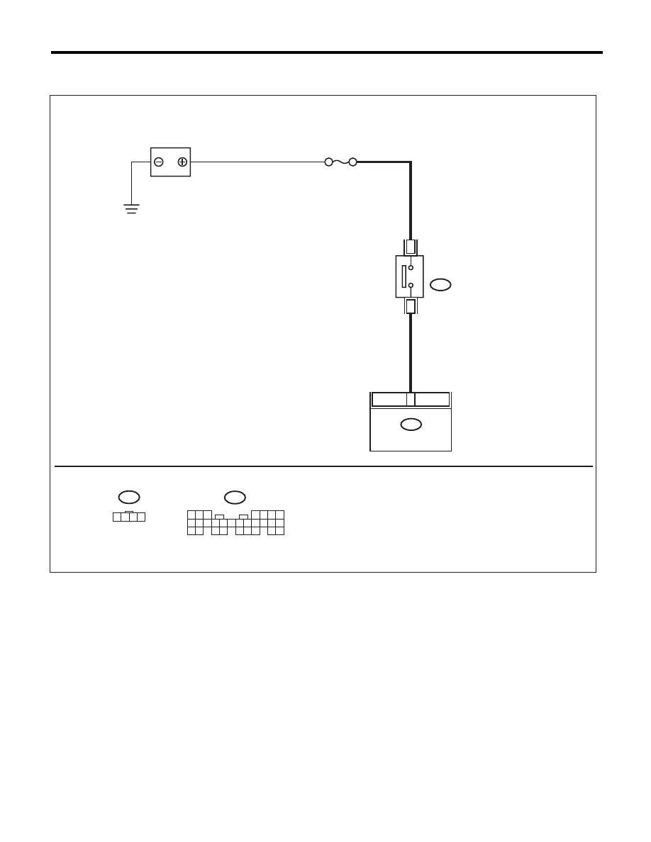
2. CHECK KEY SWITCH CIRCUIT
WIRING DIAGRAM:
B350
B281
M/B No.14
C7
3
4
C:
5 6 7
8
2
1
9
4
3
10
24
22 23
25
11 12 13 14 15
26
27 28
16 17 18 19
20 21
B281
C:
B350
1 2 3 4
BATTERY
KEY WARNING SWITCH
BODY INTEGRATED
UNIT
IM-00200
Нет комментариевНе стесняйтесь поделиться с нами вашим ценным мнением.
Текст