Subaru Legacy IV (2008 year). Service manual — part 452
FU(H6DO)-27
EGR Valve
FUEL INJECTION (FUEL SYSTEMS)
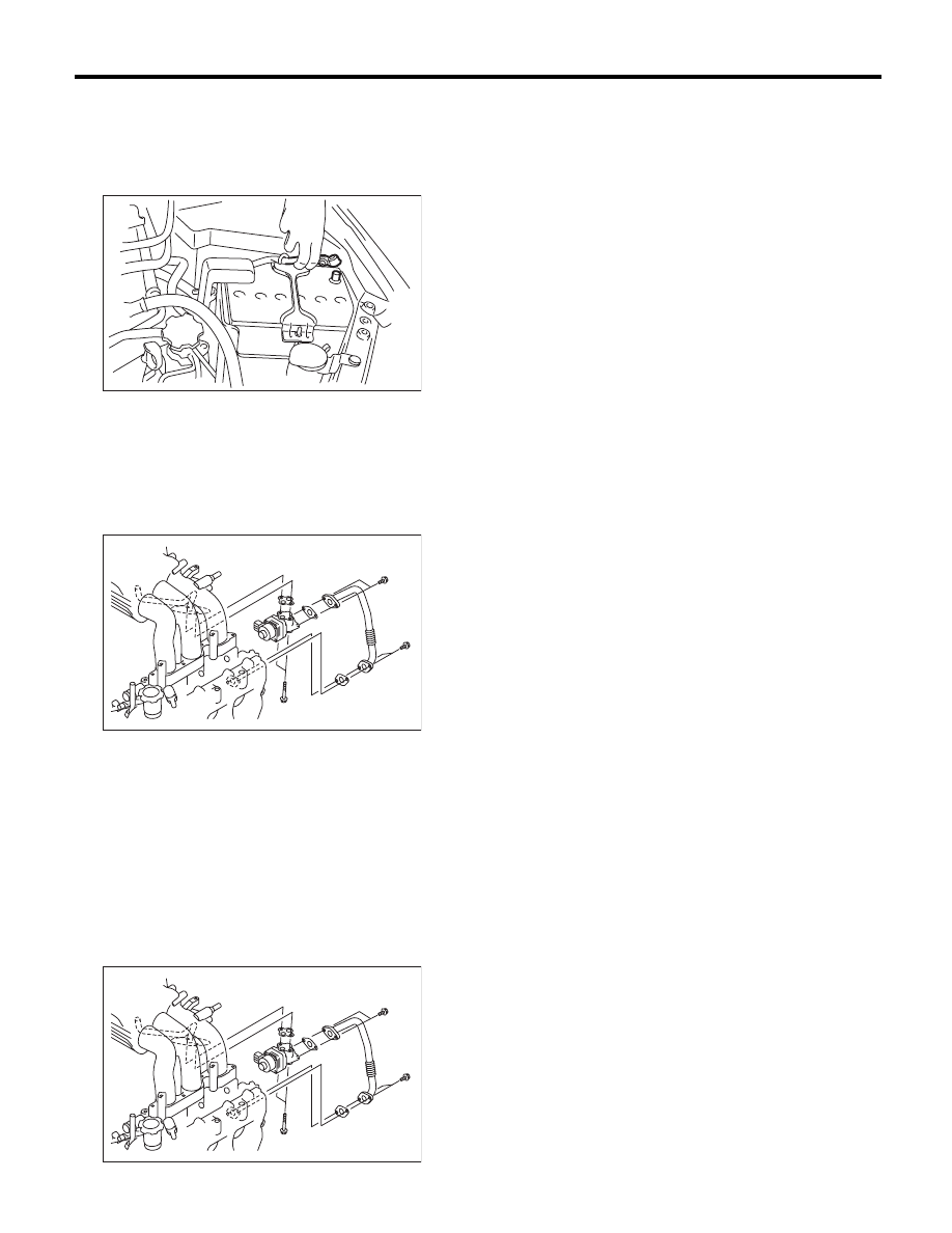
11.EGR Valve
A: REMOVAL
1) Remove the collector cover.
2) Disconnect the ground cable from battery.
3) Remove the air intake chamber. <Ref. to
IN(H6DO)-7, REMOVAL, Air Intake Chamber.>
4) Remove the starter. <Ref. to SC(H4SO)-6, RE-
MOVAL, Starter.>
5) Remove the EGR pipe from EGR valve and cyl-
inder head.
6) Remove the EGR valve from intake manifold.
7) Disconnect the connector from the EGR valve.
B: INSTALLATION
Install in the reverse order of removal.
NOTE:
Use a new gasket.
Tightening torque:
EGR valve
19 N·m (1.9 kgf-m, 14.0 ft-lb)
EGR pipe
6.4 N·m (0.7 kgf-m, 4.7 ft-lb)
IN-00203
FU-02133
FU-02133
FU(H6DO)-28
Fuel Injector
FUEL INJECTION (FUEL SYSTEMS)
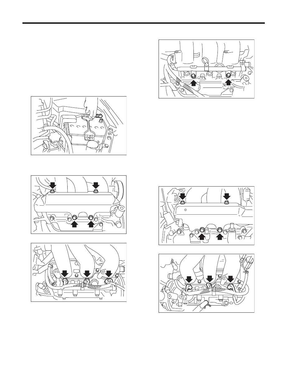
12.Fuel Injector
A: REMOVAL
1. RH SIDE
1) Remove the collector cover.
2) Release the fuel pressure. <Ref. to FU(H6DO)-
43, RELEASING OF FUEL PRESSURE, PROCE-
DURE, Fuel.>
3) Open the fuel filler lid, and remove the fuel filler
cap.
4) Disconnect the ground cable from battery.
5) Remove the air cleaner case. <Ref. to
IN(H6DO)-5, REMOVAL, Air Cleaner Case.>
6) Remove the fuel pipe protector RH.
7) Disconnect the connector from fuel injector.
8) Remove the engine harness from the fuel injec-
tor pipe RH.
9) Remove the bolt which holds fuel injector pipe
onto cylinder head.
10) Remove the fuel injector while lifting up the fuel
injector pipe.
2. LH SIDE
1) Remove the collector cover.
2) Release the fuel pressure. <Ref. to FU(H6DO)-
43, RELEASING OF FUEL PRESSURE, PROCE-
DURE, Fuel.>
3) Open the fuel filler lid, and remove the fuel filler
cap.
4) Remove the battery. <Ref. to SC(H4SO)-20,
REMOVAL, Battery.>
5) Remove the generator harness from the fuel
pipe protector LH.
6) Remove the fuel pipe protector LH.
7) Disconnect the connector from fuel injector.
8) Remove the engine harness from the fuel injec-
tor pipe LH.
IN-00203
FU-02119
FU-02134
FU-02120
FU-02117
FU-02135
FU(H6DO)-29
Fuel Injector
FUEL INJECTION (FUEL SYSTEMS)
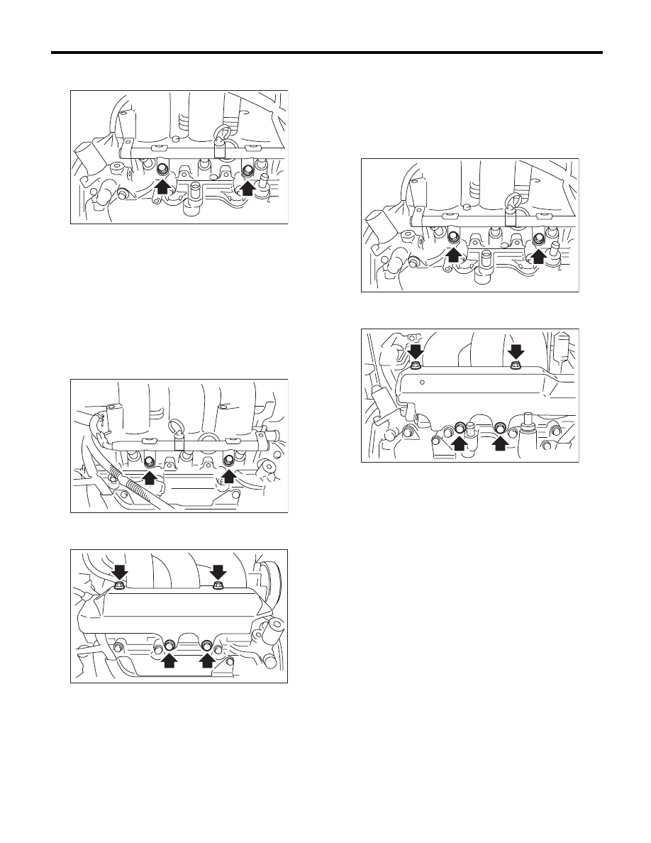
9) Remove the bolt which holds fuel injector pipe
onto cylinder head.
10) Remove the fuel injector while lifting up the fuel
injector pipe.
B: INSTALLATION
1. RH SIDE
Install in the reverse order of removal.
NOTE:
Use new O-rings.
Tightening torque:
19 N·m (1.9 kgf-m, 14.0 ft-lb)
Tightening torque:
19 N·m (1.9 kgf-m, 14.0 ft-lb)
2. LH SIDE
Install in the reverse order of removal.
NOTE:
Use new O-rings.
Tightening torque:
19 N·m (1.9 kgf-m, 14.0 ft-lb)
Tightening torque:
19 N·m (1.9 kgf-m, 14.0 ft-lb)
FU-02118
FU-02120
FU-02119
FU-02118
FU-02117
FU(H6DO)-30
Variable Valve Lift Diagnosis Oil Pressure Switch
FUEL INJECTION (FUEL SYSTEMS)
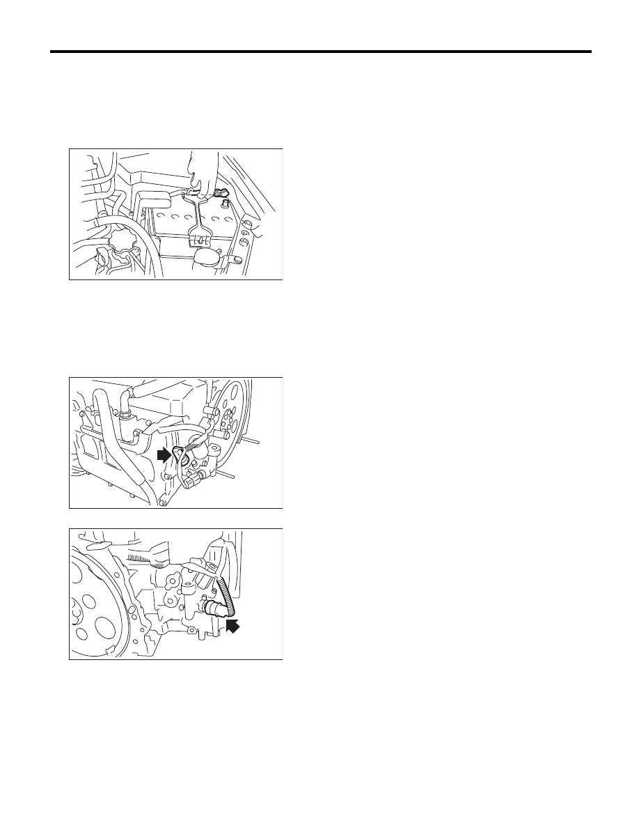
13.Variable Valve Lift Diagnosis
Oil Pressure Switch
A: REMOVAL
1) Remove the collector cover.
2) Disconnect the ground cable from battery.
3) Remove the air intake chamber. <Ref. to
IN(H6DO)-7, REMOVAL, Air Intake Chamber.>
4) Disconnect the connector from the variable
valve lift diagnosis oil pressure switch.
5) Remove the variable valve lift diagnosis oil pres-
sure switch.
• LH side
• RH side
B: INSTALLATION
Install in the reverse order of removal.
NOTE:
Apply liquid gasket to the variable valve lift diagno-
sis oil pressure switch threads.
Liquid gasket:
THREE BOND 1324 (Part No. 004403042) or
equivalent
Tightening torque:
17 N·m (1.7 kgf-m, 12.5 ft-lb)
IN-00203
FU-02136
FU-02137
Нет комментариевНе стесняйтесь поделиться с нами вашим ценным мнением.
Текст