Subaru Legacy IV (2008 year). Service manual — part 518

EN(H6DO)(diag)-45
Inspection Mode
ENGINE (DIAGNOSTICS)
P0335
Crankshaft Position Sensor “A” Circuit
—
P0336
Crankshaft Position Sensor “A” Circuit Range/Performance
—
P0340
Camshaft Position Sensor “A” Circuit (Bank 1 or Single Sensor)
—
P0345
Camshaft Position Sensor “A” Circuit (Bank 2)
—
P0447
Evaporative Emission Control System Vent Control Circuit Open
—
P0448
Evaporative Emission Control System Vent Control Circuit Shorted
—
P0452
Evaporative Emission Control System Pressure Sensor Low Input
—
P0453
Evaporative Emission Control System Pressure Sensor High Input
—
P0458
Evaporative Emission System Purge Control Valve Circuit Low
—
P0462
Fuel Level Sensor “A” Circuit Low
—
P0463
Fuel Level Sensor “A” Circuit High
—
P0500
Vehicle Speed Sensor “A”
—
P0512
Starter Request Circuit
—
P0513
Incorrect Immobilizer Key
—
P0600
Serial Communication Link
—
P0604
Internal Control Module Random Access Memory (RAM) Error
—
P0605
Internal Control Module Read Only Memory (ROM) Error
—
P0607
Throttle Control System Circuit Range/Performance
—
P0638
Throttle Actuator Control Range/Performance (Bank 1)
—
P0700
Transmission Control System (MIL Request)
—
P1152
O2 Sensor Circuit Range/Performance (Low) (Bank1 Sensor1)
—
P1153
O2 Sensor Circuit Range/Performance (High) (Bank1 Sensor1)
—
P1154
O2 Sensor Circuit Range/Performance (Low) (Bank 2 Sensor 1)
—
P1155
O2 Sensor Circuit Range/Performance (High) (Bank 2 Sensor 1)
—
P1160
Return Spring Failure
—
P1400
Fuel Tank Pressure Control Solenoid Valve Circuit Low
—
P1420
Fuel Tank Pressure Control Sol. Valve Circuit High
—
P1560
Back-Up Voltage Circuit Malfunction
—
P1570
Antenna
—
P1571
Reference Code Incompatibility
—
P1572
IMM Circuit Failure (Except Antenna Circuit)
—
P1574
Key Communication Failure
—
P1576
EGI Control Module EEPROM
—
P1577
IMM Control Module EEPROM
—
P1578
Meter Failure
—
P2088
Intake Camshaft Position Actuator Control Circuit Low (Bank 1)
—
P2089
Intake Camshaft Position Actuator Control Circuit High (Bank 1)
—
P2092
Intake Camshaft Position Actuator Control Circuit Low (Bank 2)
—
P2093
Intake Camshaft Position Actuator Control Circuit High (Bank 2)
—
P2101
Throttle Actuator Control Motor Circuit Range/Performance
—
P2102
Throttle Actuator Control Motor Circuit Low
—
P2109
Throttle/Pedal Position Sensor “A” Minimum Stop Performance
—
P2122
Throttle/Pedal Position Sensor/Switch “D” Circuit Low Input
—
P2123
Throttle/Pedal Position Sensor/Switch “D” Circuit High Input
—
P2127
Throttle/Pedal Position Sensor/Switch “E” Circuit Low Input
—
P2128
Throttle/Pedal Position Sensor/Switch “E” Circuit High Input
—
P2135
Throttle/Pedal Position Sensor/Switch “A”/“B” Voltage Correlation
—
P2138
Throttle/Pedal Position Sensor/Switch “D”/“E” Voltage Correlation
—
P2227
Barometric Pressure Circuit Range/Performance
—
P2228
Barometric Pressure Circuit Low
—
P2229
Barometric Pressure Circuit High
—
DTC
Item
Condition
EN(H6DO)(diag)-46
Inspection Mode
ENGINE (DIAGNOSTICS)
1. PREPARATION FOR THE INSPECTION
MODE
1) Check battery voltage is 12 V or more and fuel
remains half [20 — 40
2 (5.3 — 10.6 US gal, 4.4 —
8.8 Imp gal)].
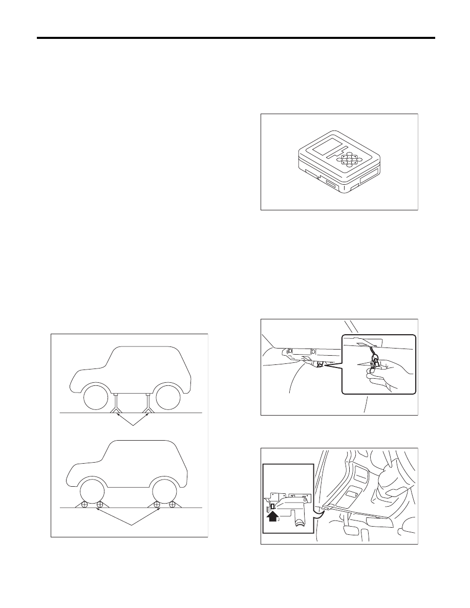
2) Lift up the vehicle using a garage jack and place
it on rigid racks, or drive the vehicle onto free roll-
ers.
WARNING:
• Before lifting up the vehicle, ensure parking
brakes are applied.
• Do not use a pantograph jack in place of a rig-
id rack.
• Secure a rope or wire to the front or rear tow-
ing hooks to prevent the lateral runout of front
wheels.
• Before rotating the wheels, make sure that
there is no one in front of the vehicle. Besides
while the wheels are rotating, make sure that no
one approaches the vehicle front side.
• Make sure that there is nothing around the
wheels. For AWD model, pay special attention
to all four wheels.
• While servicing, do not depress or release
the clutch pedal or accelerator pedal quickly re-
gardless of the engine speed. Quick operation
may cause the vehicle to drop off the free roller.
• To prevent the vehicle from slipping due to
vibration, do not place anything between rigid
rack and the vehicle.
2. SUBARU SELECT MONITOR
1) Check that no DTC remains after clearing memory.
<Ref. to EN(H6DO)(diag)-52, Clear Memory Mode.>
2) Warm up the engine.
3) Prepare the Subaru Select Monitor kit. <Ref. to
EN(H6DO)(diag)-7, PREPARATION TOOL, Gen-
eral Description.>
4) Prepare PC with Subaru Select Monitor installed.
5) Connect the USB cable between SDI (Subaru Di-
agnosis Interface) and USB port on the personal com-
puter (dedicated port for the Subaru Select Monitor).
NOTE:
The dedicated port for the Subaru Select Monitor
means the USB port which was used to install the
Subaru Select Monitor.
6) Connect the diagnosis cable to SDI.
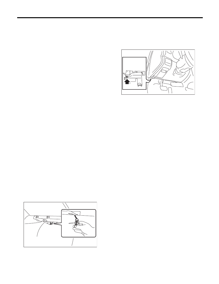
7) Connect the delivery (test) mode connector (A)
located under the glove box.
8) Connect SDI to data link connector located in the
lower portion of the instrument panel (on the driv-
er’s side).
CAUTION:
Do not connect the scan tools except for Suba-
ru Select Monitor and general scan tool.
(A) Rigid rack
(B) Free roller
EN-00041
(A)
(B)
EN-05692
PI-00201
(A)
EN-02533
EN(H6DO)(diag)-47
Inspection Mode
ENGINE (DIAGNOSTICS)
9) Start the PC.
10) Turn the ignition switch to ON (engine OFF)
and run the “PC application for Subaru Select Mon-
itor”.
11) On the «Main Menu» display screen, select the
{Each System Check}.
12) On the «System Selection Menu» display
screen, select the {Engine Control System}.
13) Click the [OK] button after the information of
engine type has been displayed.
14) On the «Engine Diagnosis» display screen, se-
lect the {Dealer Check Mode Procedure}.
15) When the «Perform Inspection (Dealer Check)
Mode?» is shown on the screen, click the [Next]
button.
16) Perform subsequent procedures as instructed
on the display screen.
• If trouble still remains in the memory, the corre-
sponding DTC appears on the display screen.
NOTE:
• For detailed operation procedures, refer to the
“PC application help for Subaru Select Monitor”.
• For details concerning DTC, refer to “List of Di-
agnostic Trouble Code (DTC)”. <Ref. to
EN(H6DO)(diag)-81, List of Diagnostic Trouble
Code (DTC).>
• Release the parking brake.
• The speed difference between front and rear
wheels may light the ABS warning light, but this
indicates no malfunctions. When engine control
diagnosis is finished, perform the ABS memory
clearance procedure of self-diagnosis system.
<Ref. to ABS(diag)-20, Clear Memory Mode.>
3. GENERAL SCAN TOOL
1) After performing the diagnostics and clearing the
memory, check that no DTC remains. <Ref. to
EN(H6DO)(diag)-52, Clear Memory Mode.>
2) Warm up the engine.
3) Connect the delivery (test) mode connector (A)
located under the glove box.
4) Connect the general scan tool to the data link
connector located in the lower portion of the instru-
ment panel (on the driver’ side).
CAUTION:
Do not connect the scan tools except for Suba-
ru Select Monitor and general scan tool.
5) Start the engine.
NOTE:
Ensure the selector lever is placed in “P” range be-
fore starting.
6) Turn the neutral position switch to ON using se-
lect lever.
7) Depress the brake pedal to turn the brake switch
ON.
8) Keep the engine speed in 2,500 — 3,000 rpm
range for 40 seconds.
9) Place the select lever in “D” range and drive the
vehicle at 5 to 10 km/h (3 to 6 MPH).
NOTE:
• For AWD model, release the parking brake.
• The speed difference between front and rear
wheels may light the ABS warning light, but this in-
dicates no malfunctions. When engine control diag-
nosis is finished, perform the ABS memory
clearance procedure of the self-diagnosis system.
<Ref. to ABS(diag)-20, Clear Memory Mode.>
10) Using the general scan tool, check DTC and
record the result(s).
NOTE:
• For detailed operation procedures, refer to the
general scan tool operation manual.
• For details concerning DTC, refer to “List of Diag-
nostic Trouble Code (DTC)”.
<Ref. to EN(H6DO)(diag)-81, List of Diagnostic
Trouble Code (DTC).>
PI-00201
(A)
EN-02533

EN(H6DO)(diag)-48
Drive Cycle
ENGINE (DIAGNOSTICS)
12.Drive Cycle
A: PROCEDURE
For the troubleshooting, there are driving patterns described below. Driving in the specified pattern allows to
diagnose malfunctioning items listed below. After the repair of the following trouble items, be sure to drive the
vehicle with the specified drive patterns to check whether the function is resumed correctly.
1. PREPARATION FOR DRIVE CYCLE
1) Check that the battery voltage is 12 V or more and fuel remains approx. half [20 — 40
2 (5.3 — 10.6 US
gal, 4.4 — 8.8 Imp gal)].
2) After performing the diagnostics and clearing the memory, check that no DTC remains. <Ref. to
EN(H6DO)(diag)-52, Clear Memory Mode.>
3) Disconnect the delivery (test) mode connector.
NOTE:
• Except for the water temperature specified at starting, be sure to carry out the diagnosis after the engine
is warmed up.
• Perform the diagnosis twice if the DTC marked with *. After completing the first diagnosis, stop the engine
and perform second diagnosis in same condition.
2. DRIVE CYCLE A — DRIVE THE VEHICLE WITH 80 KM/H (50 MPH) FOR 20 MINUTES, AND
THEN IDLE THE ENGINE FOR A MINUTE
DTC
Item
Condition
*P0125
Insufficient Coolant Temperature for Closed Loop Fuel Control
Engine coolant temperature at engine start is less
than 20°C (68°F).
*P0126
Insufficient Engine Coolant Temperature For Stable Operation
—
*P0128
Coolant Thermostat (Engine Coolant Temperature Below Ther-
mostat Regulating Temperature)
—
*P0133
O2 Sensor Circuit Slow Response (Bank 1 Sensor 1)
—
*P0153
O2 Sensor Circuit Slow Response (Bank 2 Sensor 1)
—
*P0171
System Too Lean (Bank 1)
Complete diagnosis with drive cycle B or C as well.
*P0172
System Too Rich (Bank 1)
Complete diagnosis with drive cycle B or C as well.
*P0174
System Too Lean (Bank 2)
Complete diagnosis with drive cycle B or C as well.
*P0175
System Too Rich (Bank 2)
Complete diagnosis with drive cycle B or C as well.
*P0196
Engine Oil Temperature Sensor Circuit Range/Performance
—
*P0301
Cylinder 1 Misfire Detected
Complete diagnosis with drive cycle B or C as well.
*P0302
Cylinder 2 Misfire Detected
Complete diagnosis with drive cycle B or C as well.
*P0303
Cylinder 3 Misfire Detected
Complete diagnosis with drive cycle B or C as well.
*P0304
Cylinder 4 Misfire Detected
Complete diagnosis with drive cycle B or C as well.
*P0305
Cylinder 5 Misfire Detected
Complete diagnosis with drive cycle B or C as well.
*P0306
Cylinder 6 Misfire Detected
Complete diagnosis with drive cycle B or C as well.
*P0420
Catalyst System Efficiency below Threshold (Bank 1)
—
*P0442
Evaporative Emission Control System Leak Detected (Small
Leak)
Engine coolant temperature at engine start is less
than 25°C (77°F).
*P0451
Evaporative Emission Control System Pressure Sensor
—
*P0456
Evaporative Emission Control System Leak Detected (Very
Small Leak)
Engine coolant temperature at engine start is less
than 25°C (77°F).
*P0457
Evaporative Emission Control System Leak Detected (Fuel
Cap Loose/Off)
Engine coolant temperature at engine start is less
than 25°C (77°F).
*P0464
Fuel Level Sensor Circuit Intermittent
—
P1443
Vent Control Solenoid Valve Function Problem
—
*P2096
Post Catalyst Fuel Trim System Too Lean (Bank 1)
Complete diagnosis with drive cycle B or C as well.
*P2097
Post Catalyst Fuel Trim System Too Rich (Bank 1)
Complete diagnosis with drive cycle B or C as well.
*P2098
Post Catalyst Fuel Trim System Too Lean Bank 2
Complete diagnosis with drive cycle B or C as well.
*P2099
Post Catalyst Fuel Trim System Too Rich Bank 2
Complete diagnosis with drive cycle B or C as well.
P2103
Throttle Actuator Control Motor Circuit High
Complete diagnosis with drive cycle B or C as well.
Нет комментариевНе стесняйтесь поделиться с нами вашим ценным мнением.
Текст