Subaru Legacy IV (2008 year). Service manual — part 228
FU(H4DOTC)-15
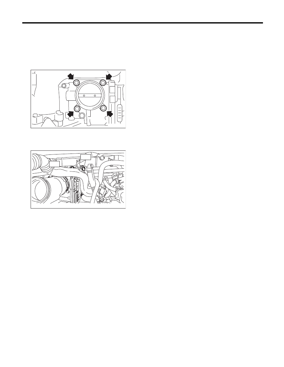
Throttle Body
FUEL INJECTION (FUEL SYSTEMS)
B: INSTALLATION
Install in the reverse order of removal.
NOTE:
Use new O-rings.
Tightening torque:
8 N·m (0.8 kgf-m, 5.9 ft-lb)
Tightening torque:
T1: 3 N·m (0.3 kgf-m, 2.2 ft-lb)
T2: 6.5 N·m (0.7 kgf-m, 4.8 ft-lb)
FU-03815
FU-04029
T2
T1
FU(H4DOTC)-16
Intake Manifold
FUEL INJECTION (FUEL SYSTEMS)
3. Intake Manifold
A: REMOVAL
1) Set the vehicle on a lift.
2) Remove the collector cover.
3) Collect the refrigerant from A/C system. <Ref. to
AC-22, PROCEDURE, Refrigerant Recovery Pro-
cedure.>
4) Release the fuel pressure. <Ref. to FU(H4DOTC)-
57, RELEASING OF FUEL PRESSURE, PROCE-
DURE, Fuel.>
5) Remove the battery. <Ref. to SC(H4SO)-20,
REMOVAL, Battery.>
6) Open the fuel filler lid, and remove the fuel filler
cap.
7) Lift up the vehicle.
8) Remove the under cover.
9) Drain approximately 3.0
2 (3.2 US qt, 2.6 Imp
qt) of coolant. <Ref. to CO(H4DOTC)-14, DRAIN-
ING OF ENGINE COOLANT, REPLACEMENT,
Engine Coolant.>
10) Remove the air intake duct and air cleaner
case. <Ref. to IN(H4DOTC)-9, REMOVAL, Air In-
take Duct.> <Ref. to IN(H4DOTC)-8, REMOVAL,
Air Cleaner Case.>
11) Remove the intercooler. <Ref. to IN(H4DOTC)-
12, REMOVAL, Intercooler.>
12) Remove the generator. <Ref. to SC(H4SO)-14,
REMOVAL, Generator.>
13) Remove the coolant filler tank. <Ref. to
CO(H4DOTC)-30, REMOVAL, Coolant Filler Tank.>
14) Disconnect the A/C pressure hoses from A/C
compressor. <Ref. to AC-40, REMOVAL, Hose and
Pipe.>
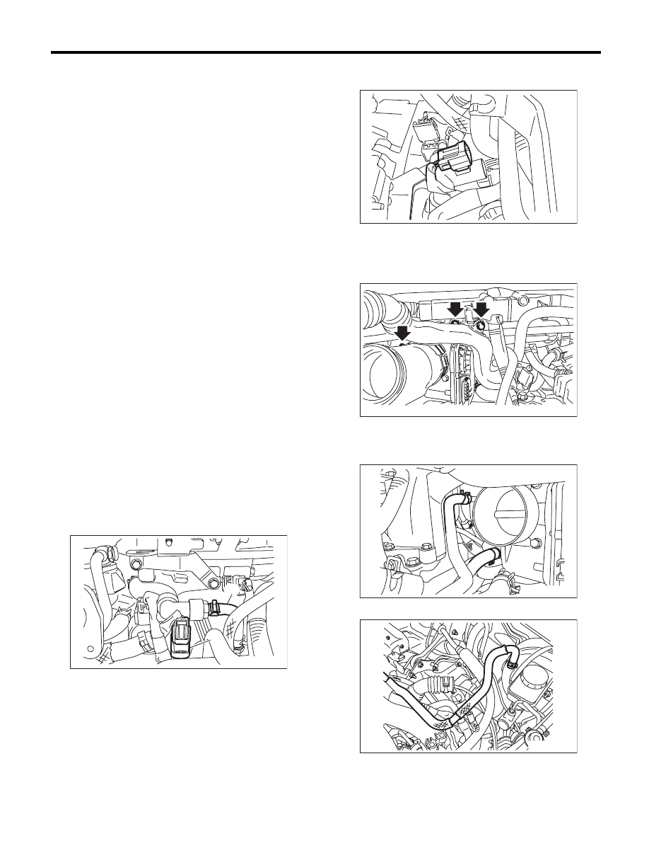
15) Disconnect the vacuum hose (A) and the con-
nector (B) from the PCV hose assembly.
16) Remove the connector from the PCV hose as-
sembly.
17) Remove the bolts which secure the air by-pass
pipe and PCV pipe to the intake manifold, and loos-
en the clamp which connects the throttle body and
duct.
18) Remove the duct from the throttle body.
19) Disconnect the engine coolant hose from throt-
tle body.
20) Disconnect the brake booster vacuum hose.
FU-03898
(B)
(A)
FU-03899
FU-03020
FU-03814
ME-03898
FU(H4DOTC)-17
Intake Manifold
FUEL INJECTION (FUEL SYSTEMS)
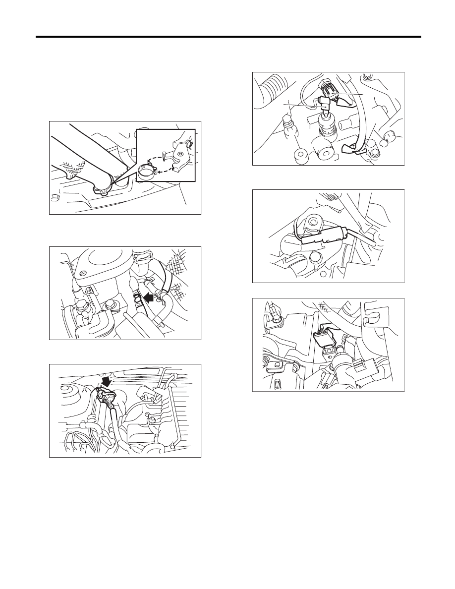
21) Disconnect the PCV hose from the rocker cov-
er.
NOTE:
Fit the cut out in the ST with the protrusion on the
clamp as shown in the figure, unlock the clamp,
and disconnect the PCV hose fastened by the
clamp.
ST
18353AA000
CLAMP PLIERS
22) Disconnect the air control hose (A) from the
wastegate actuator, and loosen the clamp that
holds the turbocharger on the intake duct.
23) Disconnect the bulk head harness connectors
from the engine harness connector.
24) Remove the engine harness connector from
the engine harness bracket.
25) Disconnect the connectors from the engine
coolant temperature sensor (A), oil pressure switch
(B) and crankshaft position sensor (C).
26) Disconnect the connector from power steering
pump switch.
27) Disconnect the knock sensor connector.
FU-03116
(A)
IN-02499
FU-02436
(A)
(B)
(C)
FU-00027
FU-03022
FU-03900
FU(H4DOTC)-18
Intake Manifold
FUEL INJECTION (FUEL SYSTEMS)
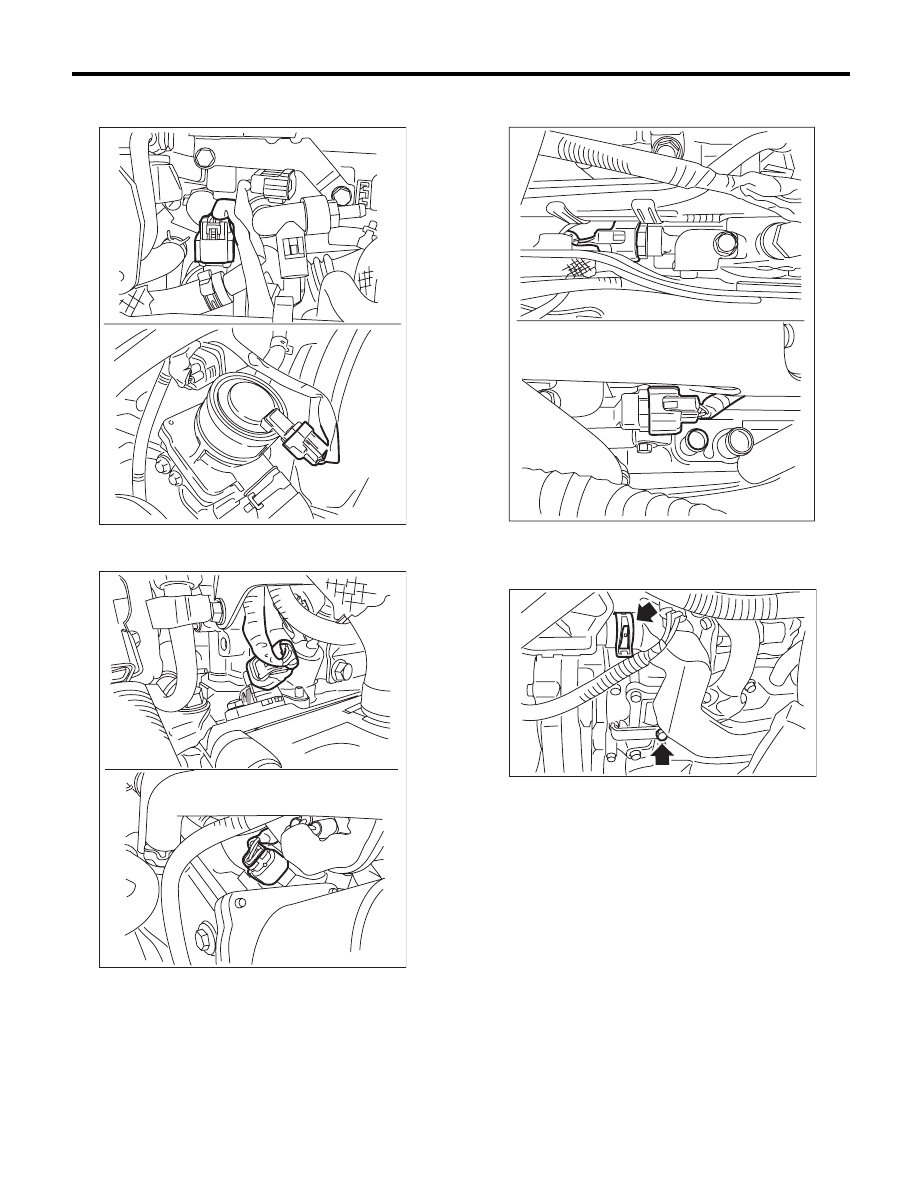
28) Disconnect the connector from the secondary
air combination valve.
29) Disconnect the connector from the camshaft
position sensor.
30) Disconnect the connector from the oil flow con-
trol solenoid valve.
31) Disconnect the air duct from the secondary air
pump, and remove the bolts that install the air duct
on the rocker cover LH.
FU-03901
FU-03902
FU-03903
FU-03905
Нет комментариевНе стесняйтесь поделиться с нами вашим ценным мнением.
Текст