Subaru Legacy IV (2008 year). Service manual — part 929
VDC(diag)-31
Warning Light Illumination Pattern
VEHICLE DYNAMICS CONTROL (VDC) (DIAGNOSTICS)
F: VDC WARNING LIGHT AND VDC OFF INDICATOR LIGHT DO NOT GO OFF
DETECTING CONDITION:
• Defective combination meter
• Defective CAN communication
• Defective engine
• VDC OFF switch is shorted.
TROUBLE SYMPTOM:
When starting the engine, VDC OFF indicator light is kept ON.
NOTE:
When pressing the VDC OFF switch for 10 seconds or more, the VDC OFF indicator light goes off and cannot
operate any more. When turning the ignition switch from OFF to ON, the OFF operation enabled status is re-
stored.
Step
Check
Yes
No
1
READ DTC.
Read the DTC. <Ref. to VDC(diag)-21, Read
Diagnostic Trouble Code (DTC).>
Is DTC displayed?
Perform the diag-
nosis according to
DTC.
Go to step 2.
2
CHECK ENGINE.
Does the malfunction indicator
light illuminate?
Repair the engine. Go to step 3.
3
CHECK ENGINE COOLANT TEMPERA-
TURE.
Warm up the engine and check if VDC warning
light and VDC OFF indicator light illumination
condition changes.
When the engine coolant tem-
perature is too low, VDC warn-
ing light and VDC OFF indicator
light illuminate. Do the lights go
off when the engine is warmed
up?
Normal operation
Go to step 4.
4
CHECK VDC OFF SWITCH.
Remove and check VDC OFF switch. <Ref. to
VDC-24, VDC OFF Switch.>
Is the VDC OFF switch normal? Go to step 5.
Replace the VDC
OFF switch.
5
CHECK LAN SYSTEM.
Perform the diagnosis for LAN system. <Ref. to
LAN(diag)-27, OPERATION, Read Diagnostic
Trouble Code (DTC).>
Is there any fault in LAN sys-
tem?
Perform the diag-
nosis according to
DTC for LAN sys-
tem.
Go to step 6.
6
CHECK COMBINATION METER.
Check the combination meter.
Is combination meter OK?
Replace the
VDCCM only.
Repair the combi-
nation meter.
VDC(diag)-32
Warning Light Illumination Pattern
VEHICLE DYNAMICS CONTROL (VDC) (DIAGNOSTICS)
G: BRAKE WARNING LIGHT DOES NOT GO OFF
DETECTING CONDITION:
• Brake warning light circuit is shorted.
• Defective sensor/connector
TROUBLE SYMPTOM:
After starting the engine, the brake warning light remains lit though the parking lever is released.
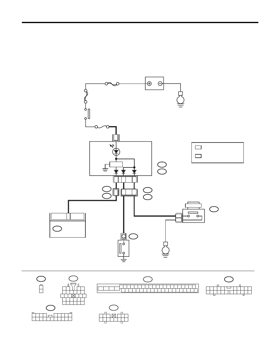
WIRING DIAGRAM:
B16
1
2
i10
2
1
3 4
6 7 8 9 10
22
21
20
19
18
17
16
15
14
13
12
11
5
A:
B:
E
MAIN SBF
SBF-6
E
No.5
8
B310
B36
B16
i1
B38
i3
B404
i10
A:
i11
B:
VDCCM & H/U
A3
A7
20
16
15
1
2
1
*
2
*
2
*
B38
1 2 3 4
5 6 7 8 9
10 11 12 13 14 15 16 17 18 19 20
i1
5 6 7 8
2
1
9
4
3
10
24
22
23
25
27
26
28
11 12 13
14 15 16
17 18 19 20 21
VDC00658
1
*
1 2 3
4 5 6
7 8 9 10 11 12 13 14
i11
B310
4 5 6 7 8 9
26 27 28 29 30
2 3
1
31 32 33 34 35 36
10 11
14 15 16 17 18 19
37 38 39 40
12 13
41 42 43 44 45 46
20 21
23
24
22
25
BATTERY
IGNITION
SWITCH
COMBINATION
METER
PARKING BRAKE
FLUID LEVEL
WARNING LIGHT
BRAKE FLUID
LEVEL SWITCH
PARKING
SWITCH
: NORMAL METER
METER WITH MID
: A8
: A4
: NORMAL METER
METER WITH MID
: B10
: A8
REVERSE
CIRCUIT
VDC(diag)-33
Warning Light Illumination Pattern
VEHICLE DYNAMICS CONTROL (VDC) (DIAGNOSTICS)
Step
Check
Yes
No
1
CHECK INSTALLATION OF VDCCM&H/U
CONNECTOR.
1) Turn the ignition switch to OFF.
2) Check that the VDCCM&H/U connector is
inserted until it is locked by clamp.
Is the connector firmly
inserted?
Go to step 2.
Insert the
VDCCM&H/U con-
nector until it is
locked by clamp.
2
READ DTC.
Read the DTC. <Ref. to VDC(diag)-21, Read
Diagnostic Trouble Code (DTC).>
Is DTC displayed?
Perform the diag-
nosis according to
DTC.
Go to step 3.
3
CHECK BRAKE FLUID AMOUNT.
Check the amount of brake fluid in the reservoir
tank of master cylinder.
Is the amount of brake fluid
between the lines of “MAX” and
“MIN”?
Go to step 4.
Replenish brake
fluid to the speci-
fied value.
4
CHECK BRAKE FLUID LEVEL SWITCH.
1) Turn the ignition switch to OFF.
2) Disconnect the level switch connector (B16)
from master cylinder.
3) Measure the resistance of master cylinder
terminals.
Terminals
No. 1 — No. 2:
Is the resistance 1 M
: or
more?
Go to step 5.
Replace the mas-
ter cylinder.
5
CHECK PARKING BRAKE SWITCH.
1) Disconnect the connector (B404) from park-
ing brake switch.
2) Release the parking brake.
3) Measure the resistance between parking
brake switch terminal and chassis ground.
Is the resistance 1 M
: or
more?
Go to step 6.
Replace the park-
ing brake switch.
6
CHECK GROUND SHORT OF HARNESS.
1) Disconnect the connectors (i10 and i11)
from the combination meter.
2) Measure the resistance between combina-
tion meter connector and chassis ground.
Connector & terminal
Normal meter model
(i10) No. 8 — Chassis ground:
(i11) No. 10 — Chassis ground:
Meter with MID model
(i10) No. 8 — Chassis ground:
(i10) No. 4 — Chassis ground:
Is the resistance 1 M
: or
more?
Go to step 7.
Repair the harness
connector between
combination meter
and brake fluid
level switch or
parking brake
switch.
7
CHECK HARNESS CONNECTOR.
1) Disconnect the connector (B310) from the
VDCCM&H/U.
2) Disconnect the connector (i10) from combi-
nation meter.
3) Measure the resistance between
VDCCM&H/U connector and combination
meter connector.
Connector & terminal
(B310) No. 8 — (i10) No. 7:
Is the resistance less than 0.5
:? Go to step 8.
Repair the harness
connector between
VDCCM&H/U and
combination meter.
8
CHECK POOR CONTACT IN CONNECTOR.
Check for poor contact in all connectors.
Is there poor contact?
Repair the connec-
tor.
Go to step 9.
9
CHECK VDCCM.
1) Connect the connector (B310) to
VDCCM&H/U.
2) Turn the ignition to ON.
3) Measure the resistance between combina-
tion meter connector and chassis ground.
Connector & terminal
(i10) No. 7 — Chassis ground:
Is the resistance less than 0.5
:? Check the combi-
nation meter.
Replace the
VDCCM only.
VDC(diag)-34
List of Diagnostic Trouble Code (DTC)
VEHICLE DYNAMICS CONTROL (VDC) (DIAGNOSTICS)
11.List of Diagnostic Trouble Code (DTC)
A: LIST
DTC
Detailed
code
Display
Content of diagnosis
Reference target
C0021
07B0H
Front Right ABS Sensor
Circuit Open or Shorted
Battery
Open/high input of front
ABS wheel speed sen-
sor RH
<Ref. to VDC(diag)-39, DTC C0021 FRONT
RIGHT ABS SENSOR CIRCUIT OPEN OR
SHORT, Diagnostic Procedure with Diagnostic
Trouble Code (DTC).>
C0022
072FH
0736H
0737H
0738H
073AH
073CH
Front Right ABS Sensor
Signal
Front ABS wheel speed
sensor RH signal mal-
function
<Ref. to VDC(diag)-42, DTC C0022 FRONT
RIGHT ABS SENSOR SIGNAL, Diagnostic Pro-
cedure with Diagnostic Trouble Code (DTC).>
C0023
06B0H
Front Left ABS Sensor
Circuit Open or Shorted
Battery
Open/high input of front
ABS wheel speed sen-
sor LH
<Ref. to VDC(diag)-39, DTC C0023 FRONT LEFT
ABS SENSOR CIRCUIT OPEN OR SHORT,
Diagnostic Procedure with Diagnostic Trouble
Code (DTC).>
C0024
062FH
0636H
0637H
0638H
063AH
063CH
Front Left ABS Sensor
Signal
Front ABS wheel speed
sensor LH signal mal-
function
<Ref. to VDC(diag)-42, DTC C0024 FRONT LEFT
ABS SENSOR SIGNAL, Diagnostic Procedure
with Diagnostic Trouble Code (DTC).>
C0025
09B0H
Rear Right ABS Sensor
Circuit Open or Shorted
Battery
Open/high input of rear
ABS wheel speed sen-
sor RH
<Ref. to VDC(diag)-39, DTC C0025 REAR RIGHT
ABS SENSOR CIRCUIT OPEN OR SHORT,
Diagnostic Procedure with Diagnostic Trouble
Code (DTC).>
C0026
092FH
0936H
0937H
0938H
093AH
093CH
Rear Right ABS Sensor
Signal
Rear ABS wheel speed
sensor RH signal mal-
function
<Ref. to VDC(diag)-42, DTC C0026 REAR RIGHT
ABS SENSOR SIGNAL, Diagnostic Procedure
with Diagnostic Trouble Code (DTC).>
C0027
08B0H
Rear Left ABS Sensor
Circuit Open or Shorted
Battery
Open/high input of rear
ABS wheel speed sen-
sor LH
<Ref. to VDC(diag)-40, DTC C0027 REAR LEFT
ABS SENSOR CIRCUIT OPEN OR SHORT,
Diagnostic Procedure with Diagnostic Trouble
Code (DTC).>
C0028
082FH
0836H
0837H
0838H
083AH
083CH
Rear Left ABS Sensor
Signal
Rear ABS wheel speed
sensor LH signal mal-
function
<Ref. to VDC(diag)-43, DTC C0028 REAR LEFT
ABS SENSOR SIGNAL, Diagnostic Procedure
with Diagnostic Trouble Code (DTC).>
C0029
0A11H
0A21H
0A42H
0A46H
0A50H
Any One of Four ABS
Sensors Signal
ABS wheel speed sen-
sor signal malfunction
in one of four wheels
<Ref. to VDC(diag)-46, DTC C0029 ANY OF
WHEEL SENSORS SIGNAL, Diagnostic Proce-
dure with Diagnostic Trouble Code (DTC).>
C0031
0DB8H
0DC0H
FR Hold Valve malfunc-
tion
Front inlet solenoid
valve RH malfunction in
VDCCM&H/U
<Ref. to VDC(diag)-48, DTC C0031 FR HOLD
VALVE MALFUNCTION, Diagnostic Procedure
with Diagnostic Trouble Code (DTC).>
C0032
0EB8H
0EC0H
FR Pressure Reducing
Valve malfunction
Front outlet solenoid
valve RH malfunction in
VDCCM&H/U
<Ref. to VDC(diag)-48, DTC C0032 FR PRES-
SURE REDUCING VALVE MALFUNCTION,
Diagnostic Procedure with Diagnostic Trouble
Code (DTC).>
Нет комментариевНе стесняйтесь поделиться с нами вашим ценным мнением.
Текст