Subaru Legacy IV (2008 year). Service manual — part 431

GD(H4DOTC)-174
Diagnostic Trouble Code (DTC) Detecting Criteria
GENERAL DESCRIPTION
CS:DTC P1410 SECONDARY AIR INJECTION SYSTEM SWITCHING VALVE
STUCK OPEN
1. OUTLINE OF DIAGNOSIS
Always detect abnormally that both combination valve electromagnetic valve and the reed valve are open
failure.
Calculate the integrated value of Max./Min. value and output voltage deviation of the secondary air delivery
pipe pressure sensor output voltage in a given time after engine start. Judge as NG if the integrated value
and the difference between Max. and Min. values are large.
2. ENABLE CONDITIONS
3. GENERAL DRIVING CYCLE
Perform continuous diagnosis when air flow amount is large during the secondary air pump stop after engine
start.
Secondary Parameters
Enable Conditions
Engine speed
t 500 rpm
and
< 10000 rpm
Elapsed time after starting the engine
t 9000 ms
After secondary air system stops
t 9000 ms
Amount of intake air
t 2 g/s (0.07 oz/s)
and
< 400 g/s (14.11 oz/s)
Battery voltage
t 10.9 V
Engine load
> 0 g/rev
After fuel cut
t 1000 ms

GD(H4DOTC)-175
Diagnostic Trouble Code (DTC) Detecting Criteria
GENERAL DESCRIPTION
4. DIAGNOSTIC METHOD
When both combination valve electromagnetic valve and the reed valve are open failure, the failure appears
as pulses in the secondary air delivery pipe pressure sensor output. Detect abnormality by capturing these
pulses using the following method.
• Abnormality Judgement
Calculate Max./Min. value of the secondary air delivery pipe pressure sensor output voltage and the sum of
the output voltage deviation for the given time. Compare the difference between Max. and Min. values with
threshold value and also compare the sum value with the threshold value. If both values exceed the threshold
value, count up NG counter and then judge as NG if the counter reaches the given times.
Time Needed for Diagnosis: 2000 ms × 20 time(s)
Malfunction Indicator Light Illumination: Illuminates as soon as a malfunction occurs.
• Normality Judgement
Judge as OK and clear NG if neither exceeds the threshold value, or if either of the two exceeds the threshold
value.
Time Needed for Diagnosis: 2000 ms
Judgement Value
Malfunction Criteria
Threshold Value
Pipe inner pressure difference between
Max. and Min.
> 0.05 V
Sum of the pipe inner pressure variation
value every 4 milliseconds
> 5 V
Barometric pressure variation value
< 26.7 kPa (200 mmHg,
7.9 inHg)
Judgement Value
Malfunction Criteria
Threshold Value
Pipe inner pressure difference between
Max. and Min.
d 0.05 V
Sum of the pipe inner pressure variation
value every 4 milliseconds
d 5 V

GD(H4DOTC)-176
Diagnostic Trouble Code (DTC) Detecting Criteria
GENERAL DESCRIPTION
CT:DTC P1418 SECONDARY AIR INJECTION SYSTEM CONTROL “A” CIRCUIT
SHORTED
1. OUTLINE OF DIAGNOSIS
Judge as NG when the ECM output level differs from the actual terminal level.
2. ENABLE CONDITIONS
3. GENERAL DRIVING CYCLE
Always perform the diagnosis continuously.
4. DIAGNOSTIC METHOD
• Abnormality Judgement
If the duration of time while the following conditions are met is longer than the time indicated, judge as NG.
Time Needed for Diagnosis: 2500 ms
Malfunction Indicator Light Illumination: Illuminates as soon as a malfunction occurs.
• Normality Judgement
Judge as OK and clear the NG if the continuous time while the following conditions are established is more
than the predetermined time.
Time Needed for Diagnosis: Less than 1 second
Secondary Parameters
Enable Conditions
None
Judgement Value
Malfunction Criteria
Threshold Value
Battery voltage
t 10.9 V
Ignition
ON
Terminal output voltage when ECM out-
puts ON signal
HIGH
Judgement Value
Malfunction Criteria
Threshold Value
Battery voltage
t 10.9 V
Ignition
ON
Terminal output voltage when ECM out-
puts ON signal
LOW
GD(H4DOTC)-177
Diagnostic Trouble Code (DTC) Detecting Criteria
GENERAL DESCRIPTION
CU:DTC P1420 FUEL TANK PRESSURE CONTROL SOL. VALVE CIRCUIT HIGH
1. OUTLINE OF DIAGNOSIS
Detect the open/short circuit of pressure control solenoid valve.
Judge as NG when ECM output level is different from actual terminal level.
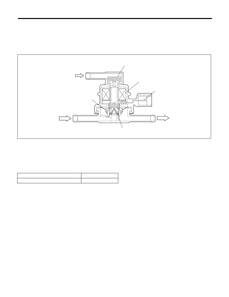
2. COMPONENT DESCRIPTION
3. ENABLE CONDITION
4. GENERAL DRIVING CYCLE
Always perform the diagnosis after starting the engine.
(A)
Barometric pressure
(B)
Shut-off valve
(C)
To fuel tank
(1)
Filter
(3)
Connector terminal
(5)
Valve
(2)
Coil
(4)
Diaphragm
Secondary Parameters
Enable Conditions
None
EN-01759
(1)
(2)
(3)
(4)
(5)
(A)
(B)
(C)
Нет комментариевНе стесняйтесь поделиться с нами вашим ценным мнением.
Текст