Subaru Legacy IV (2008 year). Service manual — part 1107
SE-40
Power Seat System
SEATS
D: ADJUSTMENT
NOTE:
The calibration procedures apply only to the mem-
ory-equipped seat on the driver’s side.
1. CONDITIONS FOR INITIALIZATION
Perform the initializing operation to the memory
module when the following conditions are met.
• When the seat was removed from vehicle.
• When the memory module was replaced.
• When the slide rail assembly or reclining motor
assembly was removed or replaced.
• When the pulse generated while the seat is mov-
ing differs from the actual distance. (When memory
replay operation is not normally carried out)
2. INITIALIZATION PROCEDURE
NOTE:
• Initialize the records inside the module by per-
forming all the following steps regardless the item
order.
• Buzzer sounds once when keeping the switch
operation for three seconds with each seat in lock*
status.
• After the completion of all items for initialization
process, the buzzer sounds three times when fin-
ishing the final operation and turning the switch
from ON to OFF.
1) Move the seat rearward using the slide switch,
and keep the seat lock* status for 3 seconds or
more.
2) Move the seat downward using tilt switch, and
keep the seat lock* status for three seconds or
more.
3) Move the seat downward using lifter switch, and
keep the seat lock* status for three seconds or
more.
4) Tilt the seatback forward using reclining switch,
and keep the seat lock* status for three seconds or
more.
*: Seat lock is the status that there is no pulse out-
put from the encoder within the specified period of
time although it reaches the movable position end.
NOTE:
When the following conditions are met, the initializ-
ing operation is cancelled even though the proce-
dure is carried out halfway.
• Any operation interval between each initialization
procedures from 1) to 4) exceeded 10 seconds.
• All operations throughout initialization procedure
1) to 4) was not performed.
• During initialization procedure, power supply
was cut off, or the voltage to the memory module
exceeded the range of operating voltage.
SL-2
General Description
SECURITY AND LOCKS
1. General Description
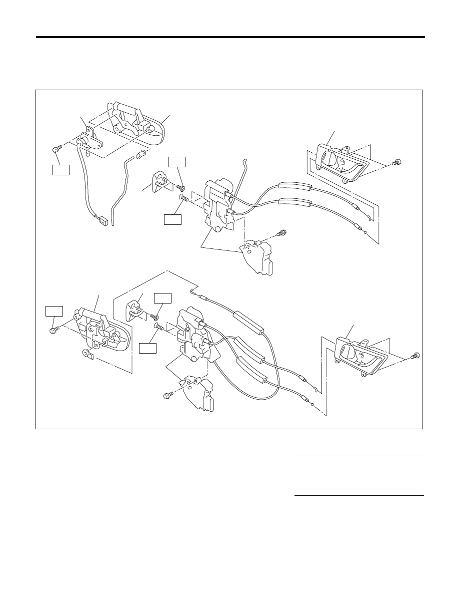
A: COMPONENT
1. DOOR LOCK ASSEMBLY
(A)
Front
(B)
Rear
(1)
Inner remote ASSY
(4)
Key cylinder (switch)
Tightening torque:N·m (kgf-m, ft-lb)
(2)
Front door latch and door lock
actuator ASSY
(5)
Striker
T1: 6.5 (0.66, 4.8)
(6)
Rear door latch and door lock
actuator ASSY
T2: 7.5 (0.76, 5.5)
(3)
Door outer handle
T3: 18 (1.8, 13.3)
SL-00394
T2
T3
T1
(5)
(2)
(3)
T2
(3)
(1)
(A)
(B)
(1)
T3
T1
(5)
(6)
(4)
SL-3
General Description
SECURITY AND LOCKS
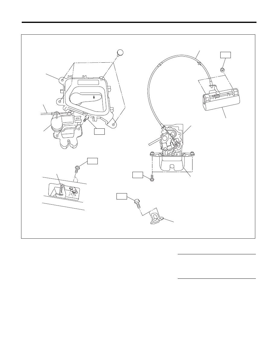
2. TRUNK LID AND REAR GATE LOCK
(A)
Trunk
(B)
Rear gate
(1)
Cable
(5)
Rear gate outer handle
Tightening torque:N·m (kgf-m, ft-lb)
(2)
Striker
(6)
Rear gate lock actuator
T1: 7.5 (0.76, 5.5)
(3)
Trunk lid lock ASSY
(7)
Rear gate latch
T2: 18 (1.8, 13.3)
(4)
Trunk lid release handle
T3: 25 (2.5, 18.4)
SL-00380
(2)
T3
T2
T1
(1)
(4)
(A)
(B)
(3)
(1)
(6)
(5)
(7)
(2)
T1
T1
SL-4
General Description
SECURITY AND LOCKS
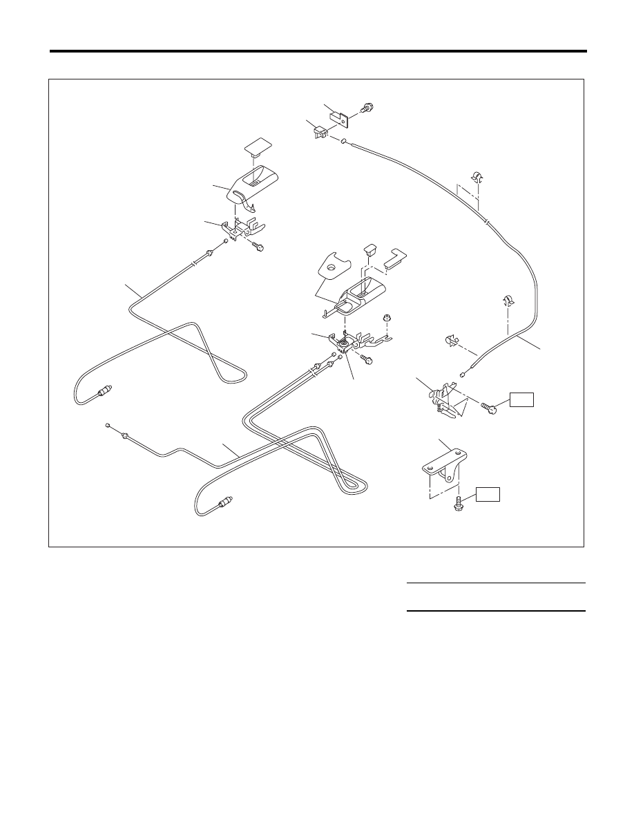
3. FRONT HOOD LOCK AND REMOTE OPENERS
(A)
Sedan model
(B)
Wagon model
(C)
Hood
(1)
Front hood lock ASSY
(5)
Cover
Tightening torque:N·m (kgf-m, ft-lb)
(2)
Lever ASSY
(6)
Pull handle ASSY
T: 33 (3.36, 24.2)
(3)
Lever ASSY bracket
(7)
Key cylinder
(4)
Cable
(8)
Striker
SL-00381
(2)
(5)
(6)
(7)
(B)
(C)
(A)
(4)
(4)
(1)
(3)
(5)
(6)
(4)
T
(8)
T
Нет комментариевНе стесняйтесь поделиться с нами вашим ценным мнением.
Текст