Subaru Legacy IV (2008 year). Service manual — part 299
EN(H4DOTC)(diag)-17
Engine Control Module (ECM) I/O Signal
ENGINE (DIAGNOSTICS)
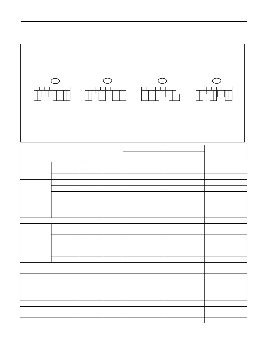
5. Engine Control Module (ECM) I/O Signal
A: ELECTRICAL SPECIFICATION
Contents
Connector
No.
Terminal
No.
Signal (V)
Note
Ignition SW ON
(engine OFF)
Engine ON
(idling)
Crankshaft
position sensor
Signal (+)
B134
13
0
–7 — +7
Waveform
Signal (–)
B134
14
0
0
—
Shield
B134
24
0
0
—
Rear oxygen
sensor
Signal
B135
4
0
0 — 0.9
—
Shield
B135
1
0
0
—
Ground
(sensor)
B135
30
0
0
—
Front oxygen
(A/F) sensor
heater
Signal 1
B136
3
—
—
Waveform
Signal 2
B136
2
—
—
Waveform
Rear oxygen sensor heater signal
B136
4
0 — 13
12 — 14
Waveform
Engine coolant
temperature
sensor
Signal
B134
34
1.0 — 1.4
1.0 — 1.4
After engine is
warmed up.
Ground
(sensor)
B134
29
0
0
After engine is
warmed up.
Air flow sensor
Signal
B135
26
—
0.3 — 4.5
—
Shield
B135
35
0
0
—
Ground
B135
34
0
0
—
Intake air temperature sensor
signal
B135
18
0.3 — 4.6
0.3 — 4.6
—
Wastegate control solenoid
valve
B137
27
0 or 10 — 13
0 or 12 — 14
Waveform
Starter switch
B136
32
0
0
Cranking: 8 — 14
A/C switch
B136
24
ON: 10 — 13
OFF: 0
ON: 12 — 14
OFF: 0
—
Ignition switch
B135
19
10 — 13
12 — 14
—
Neutral position switch (AT / MT)
B136
31
ON: 0
OFF: 10 — 13
ON: 0
OFF: 12 — 14
—
Delivery (test) mode connector
B135
27
10 — 13
13 — 14
When connected: 0
EN-05288
B134
5
6
7
8
2
1
9
4
3
10
24
22
23
25
11
12
13
14
15
26
27
28
16
17
18
19
20
21
33
34
29
32
30
31
B136
5
6
7
8
2
1
9
4
3
10
24
22
23
25
11
12
13
14
15
26
27
28
16
17
18
19
20
21
33
34
29
32
30
31
35
B135
5
6
7
8
2
1
9
4
3
10
24
22
23
25
11
12
13
14
15
26
27
28
16
17
18
19
20
21
29
30
31
32
33
34
35
B137
5
6
7
8
2
1
9
4
3
10
22
23
11
12
13
14
15
24
25
26
16
17
18
19
20
21
27
28
29
30
31
TO A:
TO B:
TO C:
TO D:

EN(H4DOTC)(diag)-18
Engine Control Module (ECM) I/O Signal
ENGINE (DIAGNOSTICS)
Knock sensor
Signal
B134
15
2.8
2.8
—
Shield
B134
25
0
0
—
Back-up power supply
B135
5
10 — 13
12 — 14
Ignition switch “OFF”:
10 — 13
Control module power supply
B134
7
10 — 13
12 — 14
—
B135
2
10 — 13
12 — 14
—
Sensor power supply
B134
19
5
5
—
Ignition control
#1
B137
18
0
12 — 14
Waveform
#2
B137
19
0
12 — 14
Waveform
#3
B137
20
0
12 — 14
Waveform
#4
B137
21
0
12 — 14
Waveform
Fuel injector
#1
B137
8
10 — 13
1 — 14
Waveform
#2
B137
9
10 — 13
1 — 14
Waveform
#3
B137
10
10 — 13
1 — 14
Waveform
#4
B137
11
10 — 13
1 — 14
Waveform
Fuel pump con-
trol unit
Signal 1
B135
33
10 — 13
12 — 14
—
Signal 2
B136
12
0 or 5
0 or 5
Waveform
A/C relay control
B136
9
ON: 0.5 or less
OFF: 10 — 13
ON: 0.5 or less
OFF: 12 — 14
—
Radiator fan relay 1 control
B136
18
ON: 0.5 or less
OFF: 10 — 13
ON: 0.5 or less
OFF: 12 — 14
—
Radiator fan relay 2 control
B136
29
ON: 0.5 or less
OFF: 10 — 13
ON: 0.5 or less
OFF: 12 — 14
Model with A/C only
Malfunction indicator light
B136
11
—
—
Light “ON”: 1 or less
Light “OFF”: 10 — 14
Engine speed output
B136
22
—
0 — 13 or more
Waveform
Purge control solenoid valve 1
B137
29
ON: 1 or less
OFF: 10 — 13
ON: 1 or less
OFF: 12 — 14
Waveform
Purge control solenoid valve 2
B136
7
ON: 1 or less
OFF: 10 — 13
ON: 1 or less
OFF: 12 — 14
Waveform
Manifold abso-
lute pressure
sensor
Signal
B134
6
1.7 — 2.4
1.1 — 1.6
—
Power supply
B134
19
5
5
Ground
(sensor)
B134
29
0
0
Power steering oil pressure
switch
B134
33
10 — 13
ON: 0
OFF: 12 — 14
—
Front oxygen (A/F) sensor signal
(+)
B135
9
2.8 — 3.2
2.8 — 3.2
—
Front oxygen (A/F) sensor signal
(–)
B135
8
2.4 — 2.7
2.4 — 2.7
—
Front oxygen (A/F) sensor
shield
B135
1
0
0
—
SSM communication line
B136
16
1 or less
mo 4 or
more
1 or less
mo 4 or
more
—
Intake camshaft position sensor
(LH)
B134
21
0 or 5
0 or 5
Waveform
Intake camshaft position sensor
(RH)
B134
11
0 or 5
0 or 5
Waveform
Intake camshaft position sensor
ground
B134
22
0
0
—
Contents
Connector
No.
Terminal
No.
Signal (V)
Note
Ignition SW ON
(engine OFF)
Engine ON
(idling)

EN(H4DOTC)(diag)-19
Engine Control Module (ECM) I/O Signal
ENGINE (DIAGNOSTICS)
Electric
throttle control
Main
B134
18
0.64 — 0.72
Fully opened: 3.96
0.64 — 0.72
(After engine is
warmed up.)
Fully closed: 0.6
Fully opened: 3.96
Sub
B134
28
1.51 — 1.58
Fully opened: 4.17
1.51 — 1.58
(After engine is
warmed up.)
Fully closed: 1.48
Fully opened: 4.17
Power supply
B134
19
5
5
—
Ground
(sensor)
B134
29
0
0
—
Electronic throttle control motor
(+)
B137
5
Duty waveform
Duty waveform
Drive frequency:
500 Hz
Electronic throttle control motor
(–)
B137
4
Duty waveform
Duty waveform
Drive frequency:
500 Hz
Electronic throttle control motor
power supply
B136
1
10 — 13
12 — 14
—
Electronic throttle control motor
relay
B136
21
ON: 0
OFF: 10 — 13
ON: 0
OFF: 12 — 14
When ignition switch
is turned to ON: ON
Intake AVCS
solenoid (LH)
Signal (+)
B137
15
ON: 10 — 13
OFF: 0
ON: 12 — 14
OFF: 0
—
Signal (–)
B137
14
0
0
—
Intake AVCS
solenoid (RH)
Signal (+)
B137
17
ON: 10 — 13
OFF: 0
ON: 12 — 14
OFF: 0
—
Signal (–)
B137
16
0
0
—
Accelerator
pedal position
sensor
Main sensor
signal
B135
23
Fully closed: 1
Fully opened: 3.3
Fully closed: 1
Fully opened: 3.3
—
Main power
supply
B135
21
5
5
—
Ground
(main sensor)
B135
29
0
0
—
Shield
B136
6
0
0
—
Sub sensor
signal
B135
31
Fully closed: 1
Fully opened: 3.3
Fully closed: 1
Fully opened: 3.3
—
Sub power
supply
B135
22
5
5
—
Ground
(sub sensor)
B135
30
0
0
—
Starter relay
B136
20
ON: 0
OFF: 10 — 13
ON: 0
OFF: 12 — 14
ON: cranking
A/C middle pressure switch
B136
33
ON: 0
OFF: 10 — 13
ON: 0
OFF: 12 — 14
—
Clutch switch
B136
25
When clutch pedal is
depressed: 0
When clutch pedal is
released: 10 — 13
When clutch pedal is
depressed: 0
When clutch pedal is
released: 12 — 14
—
Brake switch 1
B135
20
When brake pedal is
depressed: 0
When brake pedal is
released: 10 — 13
When brake pedal is
depressed: 0
When brake pedal is
released: 12 — 14
—
Brake switch 2
B135
28
When brake pedal is
depressed: 10 — 13
When brake pedal is
released: 0
When brake pedal is
depressed: 12 — 14
When brake pedal is
released: 0
—
Contents
Connector
No.
Terminal
No.
Signal (V)
Note
Ignition SW ON
(engine OFF)
Engine ON
(idling)

EN(H4DOTC)(diag)-20
Engine Control Module (ECM) I/O Signal
ENGINE (DIAGNOSTICS)
Cruise control command switch
B135
24
When not operating:
3.5 — 4.5
When operating
RES/ACC: 2.5 — 3.5
When operating SET/
COAST: 0.5 — 1.5
When operating
CANCEL 0 — 0.5
When not operating:
3.5 — 4.5
When operating
RES/ACC: 2.5 — 3.5
When operating SET/
COAST: 0.5 — 1.5
When operating
CANCEL: 0 — 0.5
—
Cruise control main switch
B135
12
ON: 0
OFF: 5
ON: 0
OFF: 5
—
Fuel tank pressure sensor
B135
32
2.3 — 2.7
2.3 — 2.7
—
Pressure control solenoid valve
B136
28
ON: 1 or less
OFF: 10 — 13
ON: 1 or less
OFF: 12 — 14
—
Drain valve
B136
17
ON: 1 or less
OFF: 10 — 13
ON: 1 or less
OFF: 12 — 14
—
Fuel temperature sensor
B135
17
2.5 — 3.8
2.5 — 3.8
Ambient temperature:
25°C (77°F)
Immobilizer
Signal 1
B136
26
—
—
—
Signal 2
B136
34
—
—
—
CAN communication (+)
B136
27
—
—
—
CAN communication (–)
B136
35
—
—
—
AT/MT identification
B136
15
0
0
—
Blow-by leak diagnosis signal
B134
30
0
0
At the time of open
circuit (fault): 5
Tumble generator valve position
sensor signal (RH)
B134
26
Fully closed:
0.4 — 1.2
Fully opened:
2.8 — 4.6
Fully closed:
0.4 — 1.2
Fully opened:
2.8 — 4.6
—
Tumble generator valve position
sensor signal (LH)
B134
16
Fully closed:
0.4 — 1.2
Fully opened:
2.8 — 4.6
Fully closed:
0.4 — 1.2
Fully opened:
2.8 — 4.6
—
Tumble generator valve RH
(closed)
B137
23
0 or 10 — 13
0 or 12 — 14
—
Tumble generator valve LH
(closed)
B137
13
0 or 10 — 13
0 or 12 — 14
—
Tumble generator valve RH
(open)
B137
22
0 or 10 — 13
0 or 12 — 14
—
Tumble generator valve LH
(open)
B137
12
0 or 10 — 13
0 or 12 — 14
—
Secondary air
pipe pressure
sensor
Signal
B134
27
2.2 — 2.8
2.2 — 2.8
When secondary air
is inducted: 3.2 — 4.9
Power supply
B134
19
5.12
5.12
—
GND (sensor)
B134
29
0
0
—
Secondary air combination
valve relay 1
B136
30
ON: 0
OFF: 10 — 13
ON: 0
OFF: 12 — 14
—
Secondary air combination
valve relay 2
B136
19
ON: 0
OFF: 10 — 13
ON: 0
OFF: 12 — 14
—
Secondary air pump relay
B136
8
ON: 0
OFF: 10 — 13
ON: 0
OFF: 12 — 14
—
Self-shutoff control
B136
23
10 — 13
12 — 14
—
Ground (ignition system)
B137
26
0
0
—
B137
6
0
0
—
Contents
Connector
No.
Terminal
No.
Signal (V)
Note
Ignition SW ON
(engine OFF)
Engine ON
(idling)
Нет комментариевНе стесняйтесь поделиться с нами вашим ценным мнением.
Текст