Subaru Legacy IV (2008 year). Service manual — part 1238
WI-204
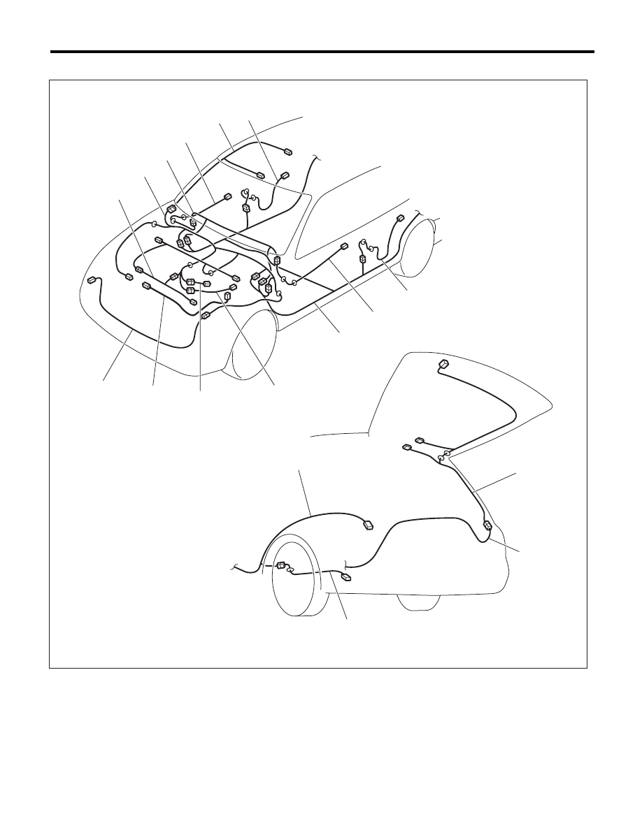
Harness Components Location
WIRING SYSTEM
2. WAGON MODEL
(1)
Front wiring harness
(6)
Rear door cord RH
(11)
Front door cord LH
(2)
Engine wiring harness
(7)
Rear wiring harness
(12)
Transmission cord
(3)
Bulkhead wiring harness
(8)
Roof cord
(13)
Rear oxygen sensor cord
(4)
Instrument panel wiring harness
(9)
Rear gate cord
(14)
Generator cord
(5)
Front door cord RH
(10)
Rear door cord LH
(15)
Fuel cord
WI-15915
(6)
(4)
(3)
(5)
(8)
(1)
(7)
(11)
(10)
(9)
(7)
(7)
(15)
(14)
(2)
(13)
(12)
WI-205
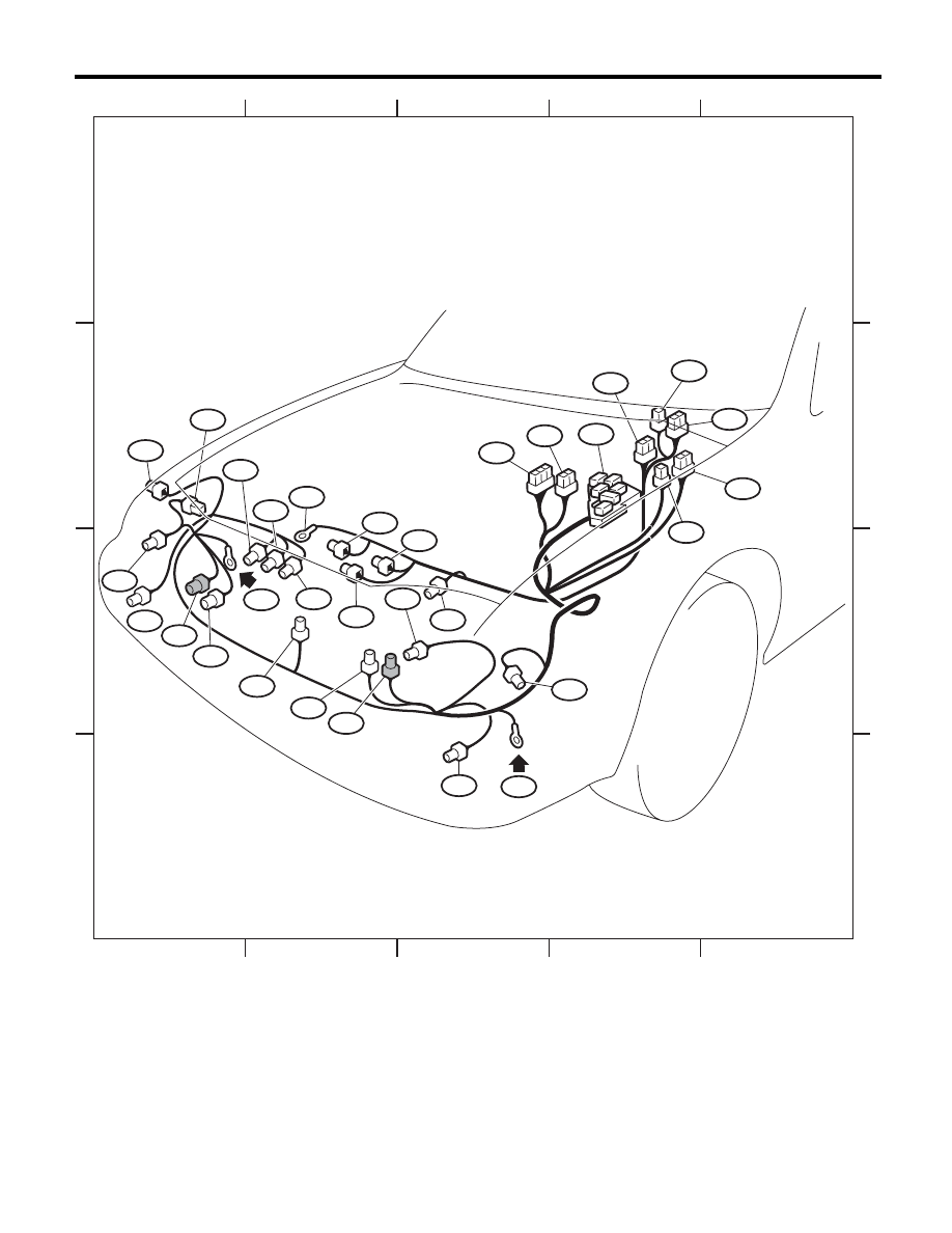
Front Wiring Harness
WIRING SYSTEM
54.Front Wiring Harness
A: LOCATION
Connector
Connecting to
No.
Pole
Color
Area
No.
Description
F3
3
Gray
B-1
Front clearance and front turn signal light RH
F5
1
Black
C-2
Horn
F6
2
Brown
C-1
Front fog light RH
F9
16
Black
B-4
Secondary air relay holder
F11
2
Gray
C-3
Secondary air pump
F16
2
Gray
C-1
Sub fan motor (H4 Turbo model)
Black
C-1
Sub fan motor (H4 Non-turbo model)
F17
2
Gray
C-2
Main fan motor (H4 Turbo model)
Black
C-2
Main fan motor (H4 Non-turbo model)
F19
3
Gray
C-3
Front clearance and front turn signal light LH
F21
2
Brown
D-3
Front fog light LH
F24
2
Black
C-2
Magnet
clutch
F25
1
C-2
Generator terminal B
F26
3
Green
C-2
Generator
F27
22
Black
B-4
Relay
holder
F35
12
Blue
B-4
Main fuse box (M/B)
F36
7
B-4
F37
20
B-4
F47
1
Black
C-2
Horn
F58
3
Gray
C-3
Headlight
LH
F59
3
Gray
C-1
Headlight
RH
F70
2
B-4
Main fuse box (M/B)
F78
2
Black
C-2
Ambient
sensor
F102
2
Black
C-2
Keyless
buzzer
F106
3
Gray
B-1
Radiator fan control unit (H6 model)
F108
18
B-4
B361
Through joint connector
F109
24
B-3
B360
F115
2
Gray
C-2
A/C lock sensor (H6 model)
: White or natural color
WI-206
Front Wiring Harness
WIRING SYSTEM
WI-15916
1
2
3
4
5
1
2
3
4
5
A
B
C
D
A
B
C
D
F6
F26
F25
F115
F11
F5
F24
F58
F35
F21
F17
F17
F78
GB-2
GB-1
F3
F106
F59
F108
F27
F109
F19
F16
F16
F37
F36
F102
F47
*2
*1
*2
*2
*1
*1: NON-TURBO MODEL
*2: TURBO MODEL
F70
F9

WI-207
Bulkhead Wiring Harness (In Engine Compartment)
WIRING SYSTEM
55.Bulkhead Wiring Harness (In Engine Compartment)
A: LOCATION
Connector
Connecting to
No.
Pole
Color
Area
No.
Description
B3
5
Black
B-2
Mass air flow and intake air temperature sensor
B6
2
Gray
B-2
Front ABS wheel speed sensor RH
B8
5
Gray
B-4
Front
wiper
motor
B10
4
Gray
B-4
Pressure
switch
B11
20
Gray
B-3
T4
Transmission (AT model)
B12
8
Gray
B-3
T3
Transmission cord (Turbo • H6 model)
12
Gray
B-3
T3
Transmission cord (SOHC model)
B14
1
Black
B-3
Starter
motor
B15
2
Gray
B-4
Front ABS wheel speed sensor LH
B16
2
Gray
B-4
Brake fluid level switch
B19
4
Green
B-2
T5
Rear oxygen sensor cord (turbo, 5AT, 5MT model)
Gray
B-2
T5
Rear oxygen sensor cord (Turbo, 6MT model)
B20
16
Brown
B-3
E1
Engine wiring harness (H6 model)
B21
54
Black
B-3
E2
Engine wiring harness
B22
16
Brown
B-3
E3
Engine wiring harness (H6 model)
B24
2
Gray
B-3
T1
Back-up light switch (H4 Non-turbo model)
B25
2
Brown
B-4
T2
Neutral position switch (H4 Non-turbo model)
B128
4
Gray
B-3
T9
Transmission harness (Turbo model)
B143
20
B-4
Main fuse box (M/B)
B144
9
Brown
B-4
B145
7
Brown
B-4
B146
2
Gray
C-4
Front washer motor
B147
2
Gray
C-4
Rear
washer
motor
B186
8
B-4
Main fuse box (M/B)
B301
26
Black
B-2
ABS
control
module
B310
46
Black
B-2
VDC control module
B321
2
Black
B-2
Hood
switch
B360
16
Gray
B-4
F109
Through joint connector
B361
14
Gray
B-4
F108
: White or natural color
Connector
Connecting to
No.
Pole
Color
Area
No.
Description
AB13
2
Yellow
C-3
Front sub sensor LH
AB16
2
Yellow
B-1
Front sub sensor RH
Нет комментариевНе стесняйтесь поделиться с нами вашим ценным мнением.
Текст