Subaru Legacy IV (2008 year). Service manual — part 589
EN(H6DO)(diag)-329
Diagnostic Procedure with Diagnostic Trouble Code (DTC)
ENGINE (DIAGNOSTICS)
EC:DTC P2102 THROTTLE ACTUATOR CONTROL MOTOR CIRCUIT LOW
DTC DETECTING CONDITION:
• Immediately at fault recognition
• GENERAL DESCRIPTION <Ref. to GD(H6DO)-193, DTC P2102 THROTTLE ACTUATOR CONTROL
MOTOR CIRCUIT LOW, Diagnostic Trouble Code (DTC) Detecting Criteria.>
TROUBLE SYMPTOM:
• Improper idling
• Poor driving performance
• Engine stalls.
CAUTION:
After repair or replacement of faulty parts, perform Clear Memory Mode <Ref. to EN(H6DO)(diag)-52,
OPERATION, Clear Memory Mode.>, and Inspection Mode <Ref. to EN(H6DO)(diag)-44, PROCEDURE,
Inspection Mode.>.
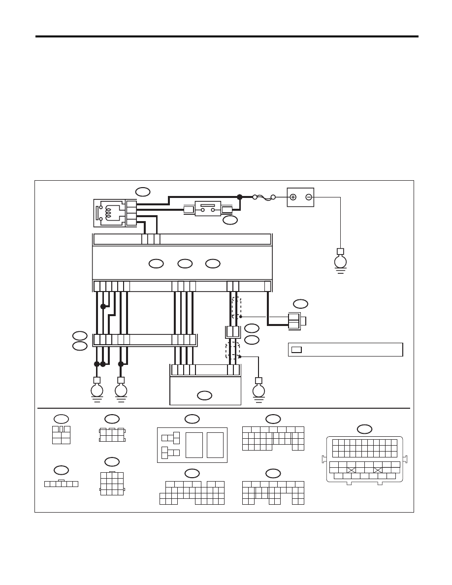
WIRING DIAGRAM:
1 2 3 4
5 6 7 8
9 10 11 12
13 14 15 16
B20
1 2 3 4 5 6
E57
1 2 3 4
5 6 7 8
B122
1 2
7 8
3
4
5
6
B362
36
52
34
35
37
E
E2
B21
E
A5
C21
C1
A29
19
E1
B20
A18
C6
A28
6
4
15
*
*
B122
16
E
38
39
20
D5
D4
A19
D7
D1
A3
D2
D3
3
E57
ELECTRONIC THROTTLE
CONTROL
2
1
5
B134
B362
5
7
6
A:
B137
B136
D:
C:
ECM
*
: TERMINAL No. OPTIONAL ARRANGEMENT
E
SBF-7
BATTERY
ELECTRONIC
THROTTLE
CONTROL RELAY
MAIN RELAY
8
6
4
B47
B47
3
4
1
2
5
6
EN-06873
16
10 11 12 13 14 15
25
24
30
9
8
7
17 18 19 20
28
21 22 23
29
32
31
1
2
3
4
5
6
27
26
33 34 35
B136
C:
5
6
7
8
2
1
9
4
3
10
22 23
11 12 13 14 15
24 25
26
16 17
18 19 20 21
27
28 29
30 31
B137
D:
5
6
7
8
2
1
9
4
3
10
24
22 23
25
11 12 13 14 15
26 27
28
16 17
18 19 20 21
33 34
29
32
30 31
B134
A:
B21
1 2 3 4 5 6 7 8 9 10 11
12 13 14 15 16 17 18 19 20 21 22
23 24 25 26 27 28 29 30 31 32 33
34
35
42
43
36
37
38
39
48
49
50
51
52
53
54
40
41
44
45
46
47

EN(H6DO)(diag)-330
Diagnostic Procedure with Diagnostic Trouble Code (DTC)
ENGINE (DIAGNOSTICS)
Step
Check
Yes
No
1
CHECK ELECTRONIC THROTTLE CON-
TROL RELAY.
1) Turn the ignition switch to OFF.
2) Remove the electronic throttle control relay.
3) Connect the battery to terminals No. 5 and
No. 6 of electronic throttle control relay.
4) Measure the resistance between electronic
throttle control relay terminals.
Terminals
No. 7 — No. 8:
Is the resistance less than 1
:? Go to step 2.
Replace the elec-
tronic throttle con-
trol relay. <Ref. to
EN(H6DO)(diag)-
8, Electrical Com-
ponent Location.>
2
CHECK POWER SUPPLY OF ELECTRONIC
THROTTLE CONTROL RELAY.
Measure the voltage between electronic throttle
control relay connector and chassis ground.
Connector & terminal
(B362) No. 7 (+) — Chassis ground (–):
Is the voltage 10 V or more?
Go to step 3.
Repair the open or
ground short circuit
of power supply
circuit.
3
CHECK HARNESS BETWEEN ECM AND
ELECTRONIC THROTTLE CONTROL RE-
LAY.
1) Disconnect the connectors from ECM.
2) Turn the ignition switch to ON.
3) Measure the voltage between electronic
throttle control relay connector and chassis
ground.
Connector & terminal
(B362) No. 6 (+) — Chassis ground (–):
Is the voltage 10 V or more?
Repair the short
circuit to power in
harness between
ECM and elec-
tronic throttle con-
trol relay.
Go to step 4.
4
CHECK HARNESS BETWEEN ECM AND
ELECTRONIC THROTTLE CONTROL RE-
LAY.
1) Turn the ignition switch to OFF.
2) Measure the resistance between electronic
throttle control relay connector and chassis
ground.
Connector & terminal
(B362) No. 6 — Chassis ground:
(B362) No. 8 — Chassis ground:
Is the resistance 1 M
: or
more?
Go to step 5.
Repair the ground
short circuit of har-
ness between
ECM and elec-
tronic throttle con-
trol relay.
5
CHECK HARNESS BETWEEN ECM AND
ELECTRONIC THROTTLE CONTROL RE-
LAY.
Measure the resistance between ECM and
electronic throttle control relay connector.
Connector & terminal
(B136) No. 21 — (B362) No. 6:
(B136) No. 1 — (B362) No. 8:
Is the resistance less than 1
:? Repair the poor
contact of ECM
connector.
Repair the open
circuit of harness
between ECM and
electronic throttle
control relay.
EN(H6DO)(diag)-331
Diagnostic Procedure with Diagnostic Trouble Code (DTC)
ENGINE (DIAGNOSTICS)
ED:DTC P2103 THROTTLE ACTUATOR CONTROL MOTOR CIRCUIT HIGH
DTC DETECTING CONDITION:
• Immediately at fault recognition
• GENERAL DESCRIPTION <Ref. to GD(H6DO)-195, DTC P2103 THROTTLE ACTUATOR CONTROL
MOTOR CIRCUIT HIGH, Diagnostic Trouble Code (DTC) Detecting Criteria.>
CAUTION:
After repair or replacement of faulty parts, perform Clear Memory Mode <Ref. to EN(H6DO)(diag)-52,
OPERATION, Clear Memory Mode.>, and Inspection Mode <Ref. to EN(H6DO)(diag)-44, PROCEDURE,
Inspection Mode.>.
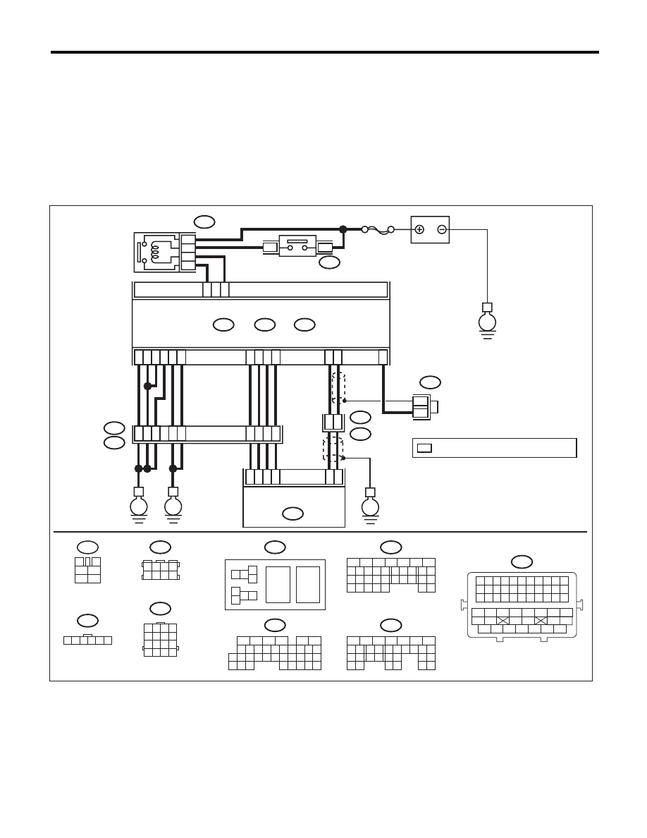
WIRING DIAGRAM:
1 2 3 4
5 6 7 8
9 10 11 12
13 14 15 16
B20
1 2 3 4 5 6
E57
1 2 3 4
5 6 7 8
B122
1 2
7 8
3
4
5
6
B362
36
52
34
35
37
E
E2
B21
E
A5
C21
C1
A29
19
E1
B20
A18
C6
A28
6
4
15
*
*
B122
16
E
38
39
20
D5
D4
A19
D7
D1
A3
D2
D3
3
E57
ELECTRONIC THROTTLE
CONTROL
2
1
5
B134
B362
5
7
6
A:
B137
B136
D:
C:
ECM
*
: TERMINAL No. OPTIONAL ARRANGEMENT
E
SBF-7
BATTERY
ELECTRONIC
THROTTLE
CONTROL RELAY
MAIN RELAY
8
6
4
B47
B47
3
4
1
2
5
6
EN-06873
16
10 11 12 13 14 15
25
24
30
9
8
7
17 18 19 20
28
21 22 23
29
32
31
1
2
3
4
5
6
27
26
33 34 35
B136
C:
5
6
7
8
2
1
9
4
3
10
22 23
11 12 13 14 15
24 25
26
16 17
18 19 20 21
27
28 29
30 31
B137
D:
5
6
7
8
2
1
9
4
3
10
24
22 23
25
11 12 13 14 15
26 27
28
16 17
18 19 20 21
33 34
29
32
30 31
B134
A:
B21
1 2 3 4 5 6 7 8 9 10 11
12 13 14 15 16 17 18 19 20 21 22
23 24 25 26 27 28 29 30 31 32 33
34
35
42
43
36
37
38
39
48
49
50
51
52
53
54
40
41
44
45
46
47

EN(H6DO)(diag)-332
Diagnostic Procedure with Diagnostic Trouble Code (DTC)
ENGINE (DIAGNOSTICS)
EE:DTC P2109 THROTTLE/PEDAL POSITION SENSOR “A” MINIMUM STOP
PERFORMANCE
NOTE:
For the diagnostic procedure, refer to DTC P2101. <Ref. to EN(H6DO)(diag)-324, DTC P2101 THROTTLE
ACTUATOR CONTROL MOTOR CIRCUIT RANGE/PERFORMANCE, Diagnostic Procedure with Diagnos-
tic Trouble Code (DTC).>
Step
Check
Yes
No
1
CHECK ELECTRONIC THROTTLE CON-
TROL RELAY.
1) Turn the ignition switch to OFF.
2) Remove the electronic throttle control relay.
3) Measure the resistance between electronic
throttle control relay terminals.
Terminals
No. 7 — No. 8:
Is the resistance 1 M
: or
more?
Go to step 2.
Replace the elec-
tronic throttle con-
trol relay. <Ref. to
EN(H6DO)(diag)-
8, Electrical Com-
ponent Location.>
2
CHECK SHORT CIRCUIT OF ELECTRONIC
THROTTLE CONTROL RELAY POWER SUP-
PLY.
1) Turn the ignition switch to ON.
2) Measure the voltage between electronic
throttle control relay connector and chassis
ground.
Connector & terminal
(B362) No. 8 (+) — Chassis ground (–):
Is the voltage 10 V or more?
Repair the short
circuit to power in
harness between
ECM and elec-
tronic throttle con-
trol relay.
Go to step 3.
3
CHECK HARNESS BETWEEN ECM AND
ELECTRONIC THROTTLE CONTROL RE-
LAY.
1) Turn the ignition switch to OFF.
2) Disconnect the connectors from ECM.
3) Measure the resistance between ECM and
chassis ground.
Connector & terminal
(B136) No. 21 — Chassis ground:
Is the resistance 1 M
: or
more?
Repair the poor
contact of ECM
connector.
Repair the ground
short circuit of har-
ness between
ECM and elec-
tronic throttle con-
trol relay.
Нет комментариевНе стесняйтесь поделиться с нами вашим ценным мнением.
Текст