Subaru Legacy IV (2008 year). Service manual — part 715
4AT(diag)-81
Diagnostic Procedure with Diagnostic Trouble Code (DTC)
AUTOMATIC TRANSMISSION (DIAGNOSTICS)
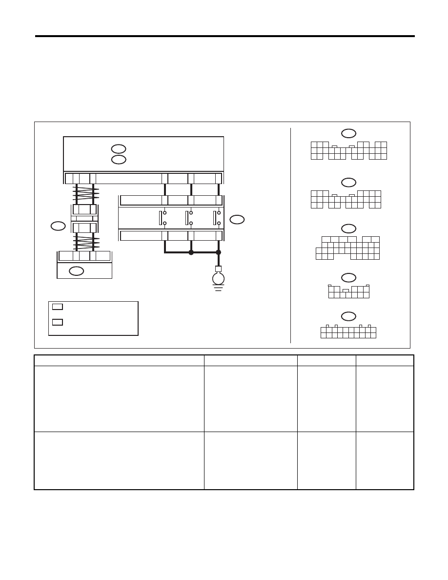
Y: DTC P1817 SPORT MODE SWITCH CIRCUIT
DTC DETECTING CONDITION:
Input signal circuit of SPORT/manual mode switch is shorted.
TROUBLE SYMPTOM:
• Manual mode can not be set.
• The SPORT indicator light does not illuminate.
• No SPORT mode occurs.
WIRING DIAGRAM:
Step
Check
Yes
No
1
CHECK BODY INTEGRATED UNIT.
1) Connect the Subaru Select Monitor to data
link connector.
2) Turn the ignition switch to ON. (engine OFF)
3) Read the DTC of the body integrated unit
using the Subaru Select Monitor. <Ref. to
LAN(diag)-12, OPERATION, Subaru Select
Monitor.>
Is DTC displayed?
Perform the diag-
nosis according to
DTC.
Go to step 2.
2
CHECK BODY INTEGRATED UNIT INPUT
SIGNAL.
1) Shift the AT select lever to “P” range.
2) Read the “Tiptronic Mode Switch” data of
the body integrated unit using the Subaru
Select Monitor. <Ref. to LAN(diag)-12, OPERA-
TION, Subaru Select Monitor.>
Is OFF displayed?
Go to step 3.
Go to step 7.
AT-04343
1
*
1
*
2
*
1
*
2
*
2
*
B281
C:
B280
B:
B20
B30
C25
C15
18
17
B116
TCM
B54
10
11
6
7
B280
B281
8
7
6
5
4
3
2
1
22
23
21
20
19
16
15
14
13
12
11
10
9
17
30
18
29
28
27
26
25
24
8
7
6
5
4
3
2
1
22 23
21
20
19
16
15
14
13
12
11
10
9
17 18
28
27
26
25
24
B116
E
B:
C:
B365
B365
B54
5
6
7 8
2
1
9
4
3
10
24
22 23
25
11 12 13 14 15
26 27
28
16
17 18 19 20 21
33 34
29
32
30
31
35
8
9
C26
UP
DO
WN
1 2
3 4 5
6 7 8 9 10 11 12
9
8
7
6
5
4
3
2
1
10
11 12 13 14 15 16 17 18 19 20
BODY INTEGRATED UNIT
AT SELECT LEVER
JOINT
CONNECTOR
SPORT/
MANUAL
MODE SWITCH
: TERMINAL No. OPTIONAL
ARRANGEMENT
AMONG 1, 2, 3, 11, 12 AND 13
: TERMINAL No. OPTIONAL
ARRANGEMENT
AMONG 8, 9, 10, 18, 19 AND 20

4AT(diag)-82
Diagnostic Procedure with Diagnostic Trouble Code (DTC)
AUTOMATIC TRANSMISSION (DIAGNOSTICS)
3
CHECK BODY INTEGRATED UNIT INPUT
SIGNAL.
1) Shift the AT select lever from “P” to “D”
range.
2) Read the “Tiptronic Mode Switch” data of
the body integrated unit using the Subaru
Select Monitor. <Ref. to LAN(diag)-12, OPERA-
TION, Subaru Select Monitor.>
Is the indication on each range
OFF?
Go to step 4.
Replace the select
lever assembly.
<Ref. to CS-23,
Select Lever.>
4
CHECK BODY INTEGRATED UNIT INPUT
SIGNAL.
1) Shift the AT select lever to SPORT mode.
2) Read the “Tiptronic Mode Switch” data of
the body integrated unit using the Subaru
Select Monitor. <Ref. to LAN(diag)-12, OPERA-
TION, Subaru Select Monitor.>
Is ON displayed?
Go to step 5.
Replace the select
lever assembly.
<Ref. to CS-23,
Select Lever.>
5
CHECK INHIBITOR SWITCH.
Shift the AT select lever from “P” to “D” range.
Is the indication of range posi-
tion indicator light in combina-
tion meter synchronized with
position of select lever?
Go to step 6.
Adjust the inhibitor
switch and select
cable. <Ref. to
4AT-46, ADJUST-
MENT, Inhibitor
Switch.> <Ref. to
CS-32, ADJUST-
MENT, Select
Cable.>
6
CHECK INPUT SIGNAL FROM TCM.
1) Shift the AT select lever from “P” to “D”
range.
2) Read the “Tiptronic Mode Switch” data of
the TCM using the Subaru Select Monitor. <Ref.
to 4AT(diag)-16, OPERATION, Subaru Select
Monitor.>
Is the indication on each range
OFF?
Even if the ATF
temperature warn-
ing light is blinking,
the circuit is in nor-
mal condition. A
temporary short
circuit of connector
or harness may be
the cause. Repair
the harness or
connector.
Replace the TCM.
<Ref. to 4AT-61,
Transmission Con-
trol Module
(TCM).>
7
CHECK HARNESS BETWEEN BODY INTE-
GRATED UNIT AND SPORT/MANUAL MODE
SWITCH.
1) Turn the ignition switch to OFF.
2) Disconnect the harness connector from
body integrated unit and AT select lever.
3) Measure the resistance between the body
integrated unit and chassis ground.
Connector & terminal
(B281) No. 26 — Chassis ground:
Is the resistance 1 M
: or
more?
Go to step 8.
Repair the short
circuit of harness
between body inte-
grated unit and
sport/manual
mode switch.
8
CHECK SPORT SHIFT SWITCH.
1) Shift the AT select lever to “P” range.
2) Measure the resistance of SPORT/manual
mode switch connector terminals.
Terminals
No. 9 — No. 8:
Is the resistance 1 M
: or
more?
Check the body
integrated unit.
Replace the select
lever assembly.
<Ref. to CS-23,
Select Lever.>
Step
Check
Yes
No
4AT(diag)-83
Diagnostic Procedure without Diagnostic Trouble Code (DTC)
AUTOMATIC TRANSMISSION (DIAGNOSTICS)
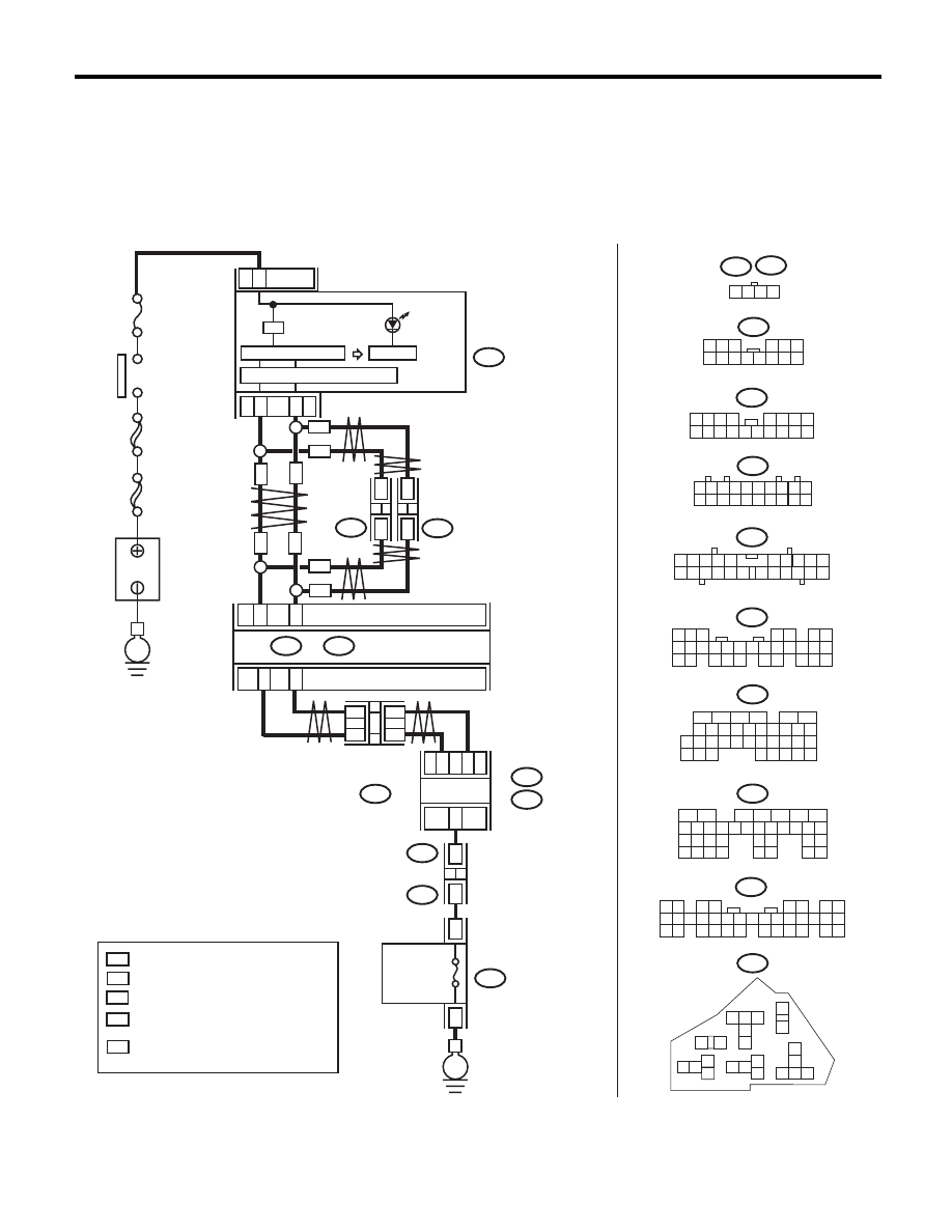
14.Diagnostic Procedure without Diagnostic Trouble Code (DTC)
A: CHECK FWD SWITCH
DIAGNOSIS:
• LED does not illuminate even with the fuse installed on FWD fuse holder.
• FWD signal circuit is open or shorted.
WIRING DIAGRAM:
AT-04899
i10
i84
F108
B361
A:
A:
B:
A1
8
A17
B10
TCM
B54
A:
B55
B:
F27
B361
F108
9
11
8
13
E
B365
B54
B55
i107
i106
1
4
3
2
F27
12
11
10
18
19
16
15
17
9
20 21 22
8
4 5
3
2
1
7
6
14
13
9
8
7
6
5
4
3
2
1
10
11 12 13 14 15 16 17 18 19 20
1
7
2 3
4 5 6
8 9 10 11 12 13 14
1
9
2 3
8
10
4
11 12 13 14 15 16
5 6 7
17 18
5
6
7
2
1
3
4
29
10 11 12 13 14 15
25
24
16
30
9
8
17 18 19
20
28
21 22 23
32
31
26 27
33
34 35
16
10 11 12 13 14 15
25
24
30
9
8
7
17 18 19 20
28
21 22 23
29
32
31
1
2
3
4
5
6
27
26
33 34 35
1 2
3 4
5 6
7 8
9 10 11 12
14 15 16 17 18 19 20 21 22 23
24 25
26 27 28 29
30 31 32 33
34 35
13
2
1
3 4
6 7 8 9 10
22
21
20
19
18
17
16
15
14
13
12
11
5
MAIN SBF
SBF-6
No.
5
E
3
21
22
i10
i84
A:
B280
B:
A26
A27
B20
B30
B365
1
*
2
*
1
*
2
*
WN
WN
ON
i107
i106
*
*
*
*
ON
WN
WN
ON
ON
:
:
1
*
2
*
:
*
:
WN
:
ON
B280
8
7
6
5
4
3
2
1
22
23
21
20
19
16
15
14
13
12
11
10
9
17
30
18
29
28
27
26
25
24
B:
CAN
JOINT
CONNECTOR
BODY INTEGRATED UNIT
IGNITION
SWITCH
CAN TRANSCEIVER & RECEIVER
MICRO COMPUTER
B
A
TTER
Y
WITH NAVIGATION
WITHOUT NAVIGATION
TERMINAL No. OPTIONAL ARRANGEMENT
AMONG 1, 2, 3, 11, 12 AND 13
TERMINAL No. OPTIONAL ARRANGEMENT
TERMINAL No. OPTIONAL ARRANGEMENT
AMONG 8, 9, 10, 18, 19 AND 20
COMBINATION
METER
AWD
WARNING
LIGHT
CAN
JOINT
CONNECTOR
CAN
JOINT
CONNECTOR
THROUGH JOINT
CONNECTOR
RELAY HOLDER
FWD FUSE
HOLDER

4AT(diag)-84
Diagnostic Procedure without Diagnostic Trouble Code (DTC)
AUTOMATIC TRANSMISSION (DIAGNOSTICS)
Step
Check
Yes
No
1
CHECK SPARE FUSE.
Is the spare fuse OK?
Go to step 2.
Replace the fuse.
2
CHECK FWD FUSE HOLDER.
Connect the Subaru Select Monitor to data link
connector.
When the fuse is inserted to
FWD fuse holder, does the LED
illuminate?
Go to step 3.
Go to step 4.
3
CHECK COMBINATION METER.
Does the AWD warning light
illuminate?
Go to INSPEC-
TION FOR
SPORT/MANUAL
MODE SWITCH.
<Ref. to 4AT(diag)-
86, CHECK
SPORT SHIFT
SWITCH, Diag-
nostic Procedure
without Diagnostic
Trouble Code
(DTC).>
Go to step 9.
4
CHECK HARNESS CONNECTOR BETWEEN
TCM AND FWD FUSE HOLDER.
1) Turn the ignition switch to OFF.
2) Disconnect the connector from TCM.
3) Measure the resistance of harness between
TCM and FWD fuse holder.
Connector & terminal
(B55) No. 10 — (F27) No. 8:
Is the resistance less than 1
:? Go to step 5.
Repair the open
circuit of harness
between TCM and
FWD fuse holder.
5
CHECK HARNESS CONNECTOR BETWEEN
FWD FUSE HOLDER AND CHASSIS
GROUND.
Measure the resistance of harness between
FWD fuse holder and chassis ground.
Connector & terminal
(F27) No. 9 — Chassis ground:
Is the resistance less than 1
:? Go to step 6.
Repair the open
circuit of harness
between FWD fuse
holder and chassis
ground.
6
CHECK HARNESS CONNECTOR BETWEEN
TCM AND FWD FUSE HOLDER.
Measure the resistance of harness connector
between TCM and body to make sure that cir-
cuit does not short.
Connector & terminal
(B55) No. 10 — Chassis ground:
Is the resistance 1 M
: or
more?
Go to step 7.
Repair the short
circuit of harness
between TCM and
FWD fuse holder.
7
CHECK INPUT SIGNAL FOR TCM.
1) Turn the ignition switch to OFF.
2) Connect the connector to TCM.
3) Turn the ignition switch to ON.
4) Measure the signal voltage for TCM with the
fuse installed to FWD fuse holder.
Connector & terminal
(B55) No. 10 (+) — Chassis ground (–):
Is the voltage less than 1 V?
Go to step 8.
Go to step 10.
8
CHECK INPUT SIGNAL FOR TCM.
Measure the signal voltage for TCM with the
fuse removed from FWD fuse holder.
Connector & terminal
(B55) No. 10 (+) — Chassis ground (–):
Is the voltage 10.5 V or more?
Go to step 9.
Replace the TCM.
<Ref. to 4AT-61,
Transmission Con-
trol Module
(TCM).>
9
CHECK BODY INTEGRATED UNIT.
Check DTC of body integrated unit.
Is DTC of CAN communication
displayed?
Perform the diag-
nosis according to
DTC.
Go to step 10.
10
CHECK COMBINATION METER.
Check the AWD warning light. <Ref. to IDI-5,
INSPECTION, Combination Meter System.>
Is the AWD warning light OK?
Go to step 11.
Replace the com-
bination meter
assembly. <Ref. to
IDI-22, Combina-
tion Meter.>
Нет комментариевНе стесняйтесь поделиться с нами вашим ценным мнением.
Текст