Subaru Legacy IV (2008 year). Service manual — part 1103
SE-24
Seat Heater System
SEATS
4. Seat Heater System
A: REMOVAL
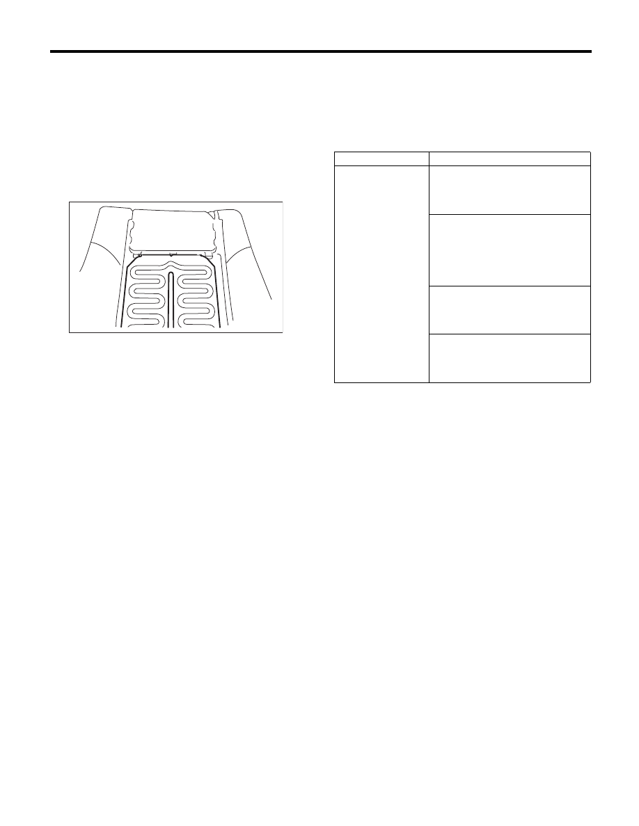
1. SEAT HEATER UNIT
1) Remove the front seats. <Ref. to SE-9, REMOV-
AL, Front Seat.>
2) Remove the backrest cover of front seat and
seat cushion cover. <Ref. to SE-10, DISASSEM-
BLY, Front Seat.>
3) Remove the seat heater unit.
2. SEAT HEATER SWITCH
1) Remove the console box. <Ref. to EI-54, RE-
MOVAL, Console Box.>
2) Remove the seat heater switch from the console
box.
B: INSTALLATION
Install in the reverse order of removal.
C: INSPECTION
1. WIRING DIAGRAM
<Ref. to WI-127, WIRING DIAGRAM, Seat Heater
System.>
2. DIAGNOSTIC CHART
3. CHECK SEAT HEATER FUSE
Remove the seat heater fuse and inspect visually.
Is the fuse blown out?
• Yes
o Replace the fuse.
• No
o Check the power supply and ground cir-
cuit.
4. CHECK POWER SUPPLY AND GROUND
CIRCUIT
1) Check power supply circuit.
(1) Disconnect the seat heater switch.
(2) Turn the ignition switch to ON.
(3) Measure the voltage between harness con-
nector terminal and chassis ground.
Connector & terminal
With SI-DRIVE
(C2) No. 12 (+) — Chassis ground (–):
Without SI-DRIVE
(C2) No. 11 (+) — Chassis ground (–):
Is the voltage 12 V or more?
• Yes
o Go to step 2.
• No
o Check the harness between the seat
heater switch and fuse.
SE-00082
Symptoms
Repair order
Seat heater does not
operate.
1. Check the fuse. <Ref. to SE-24,
CHECK SEAT HEATER FUSE,
INSPECTION, Seat Heater Sys-
tem.>
2. Check the power supply and
ground circuit for the seat heater
system. <Ref. to SE-24, CHECK
POWER SUPPLY AND GROUND
CIRCUIT, INSPECTION, Seat
Heater System.>
3. Check the thermistor circuit. <Ref.
to SE-25, CHECK THERMISTOR
CIRCUIT, INSPECTION, Seat
Heater System.>
4. Check the seat heater switch cir-
cuit. <Ref. to SE-25, CHECK SEAT
HEATER SWITCH, INSPECTION,
Seat Heater System.>
SE-25
Seat Heater System
SEATS
2) Check ground circuit.
Measure the resistance between harness connec-
tor terminal and chassis ground.
Connector & terminal
With SI-DRIVE
(C2) No. 2 — Chassis ground:
Without SI-DRIVE
(C2) No. 6 — Chassis ground:
Is the resistance less than 10
:?
• Yes
o Go to step 3.
• No
o Repair the harness.
3) Check ground circuit.
Measure the resistance between harness connec-
tor terminals.
Connector & terminal
With SI-DRIVE
(C2) No. 1 — (C2) No. 2:
(C2) No. 3 — (C2) No. 2:
Without SI-DRIVE
(C2) No. 3 — (C2) No. 6:
(C2) No. 7 — (C2) No. 6:
Is the resistance less than 10
:?
• Yes
o The power supply and ground circuit are
normal.
• No
o Repair the harness.
5. CHECK THERMISTOR CIRCUIT
1) Disconnect the seat heater switch connector.
2) Measure the resistance between harness con-
nector terminals.
Connector & terminal
Check LHD side
With SI-DRIVE
(C2) No. 8 — (C2) No. 3:
Without SI-DRIVE
(C2) No. 2 — (C2) No. 7:
Check RHD side
With SI-DRIVE
(C2) No. 6 — (C2) No. 1:
Without SI-DRIVE
(C2) No. 4 — (C2) No. 3:
Is the resistance between 1 K
: to 200 K:?
• Yes
o The thermistor circuit is normal.
• No
o The harness or thermistor is faulty.
6. CHECK SEAT HEATER SWITCH
1) Check thermistor output voltage
(1) Turn the ignition switch to ON.
(2) Measure the voltage between the seat heat-
er switch and chassis ground.
Connector & terminal:
LHD side seat
With SI-DRIVE
(C2) No. 8 (+) — Chassis ground (–):
Without SI-DRIVE
(C2) No. 2 (+) — Chassis ground (–):
RHD side seat
With SI-DRIVE
(C2) No. 6 (+) — Chassis ground (–):
Without SI-DRIVE
(C2) No. 4 (+) — Chassis ground (–):
Is the voltage 1.5 V or more?
• Yes
o Go to step 2.
• No
o Replace the seat heater switch.
2) Check output voltage
(1) Turn the ignition switch to ON.
(2) Measure the voltage between the seat heat-
er switch and chassis ground when turning the
switch to a position other than OFF.
Connector & terminal:
LHD side seat
With SI-DRIVE
(C2) No. 9 (+) — Chassis ground (–):
Without SI-DRIVE
(C2) No. 1 (+) — Chassis ground (–):
RHD side seat
With SI-DRIVE
(C2) No. 7 (+) — Chassis ground (–):
Without SI-DRIVE
(C2) No. 9 (+) — Chassis ground (–):
Does the voltage fluctuate between 12 V
mo 0 V?
• Yes
o Harness faulty, open circuit of heater
or thermostat faulty.
• No
o Replace the seat heater switch.
SE-26
Power Seat System
SEATS
5. Power Seat System
A: REMOVAL
CAUTION:
When it is necessary to remove the front seat,
disconnect the ground cable from battery and
wait for 20 seconds before disconnecting the
side airbag module harness connector.
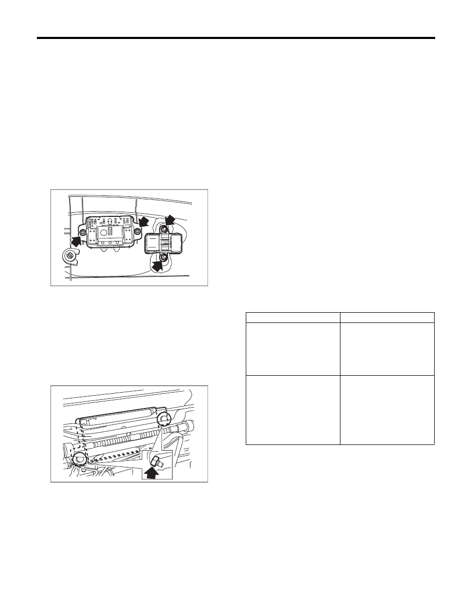
1. POWER SEAT SWITCH
1) Detach the connectors and remove the seat side
cover outside. <Ref. to SE-10, DISASSEMBLY,
Front Seat.>
2) Remove the screws to remove the power seat
switch assembly.
NOTE:
Perform the same procedure when removing the
memory switch of memory-equipped seat.
2. MEMORY MODULE
(MEMORY-EQUIPPED SEAT)
1) Lift the seat cushion by operating the switch.
2) Remove the front seat from the vehicle.
3) Remove the nut and then remove the memory
module.
B: INSTALLATION
Install in the reverse order of removal.
NOTE:
• The seat with memory function must be initial-
ized after installed. <Ref. to SE-40, ADJUST-
MENT, Power Seat System.>
• Check the following items after replacing the
memory-equipped seat or the memory module.
• AT model
1. Memory is reloaded when ignition is ON and
select lever shifted to “P” range.
2. Memory is not reloaded when ignition is ON
and set the select lever to other than “P” range.
• MT model
1. Memory feature is restored after turning igni-
tion switch to ON and pulling parking brake lever.
2. Memory feature is not restored after turning
the ignition switch to ON and pushing parking
brake lever.
C: INSPECTION
1. WIRING DIAGRAM
<Ref. to WI-118, WIRING DIAGRAM, Power Seat
System.>
2. TROUBLE SYMPTOM
• Driver’s seat (without memory)
SE-00686
SE-00687
Symptoms
Criteria
All function fails to operate.
<Ref. to SE-28, ALL FUNC-
TION FAILS TO OPERATE
(DRIVER’S SEAT, WITH-
OUT MEMORY), INSPEC-
TION, Power Seat System.>
• Power seat switch
• Power seat harness
• Body harness
A part of function does not
operate.
<Ref. to SE-29, SOME OF
THE MOTORS DO NOT
OPERATE (DRIVER’S
SEAT, WITHOUT MEM-
ORY), INSPECTION, Power
Seat System.>
• Power seat switch
• Power seat harness
• Relevant motor
SE-27
Power Seat System
SEATS
• Driver’s seat (with memory)
• Passenger’s seat
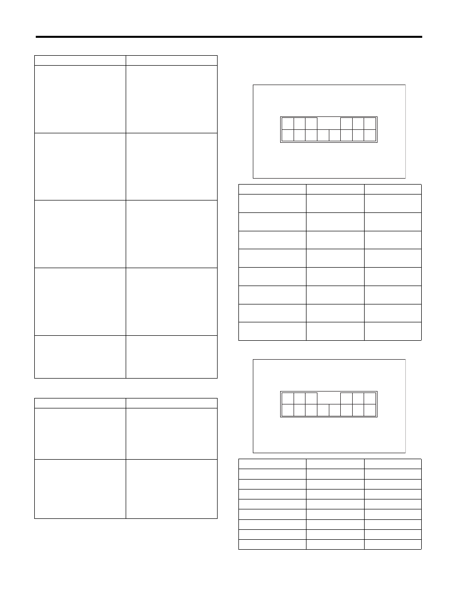
3. CHECK POWER SEAT SWITCH
Move each switch and measure the resistance be-
tween connector terminals.
• Driver’s seat (without memory)
• Driver’s seat (with memory)
Symptoms
Criteria
Does not operate by manual
operation.
<Ref. to SE-31, DOES NOT
OPERATE IN MANUAL
OPERATION (DRIVER’S
SEAT, MEMORY-
EQUIPPED), INSPECTION,
Power Seat System.>
• Power seat switch
• Power seat harness
• Body harness
• Relevant motor and
encoder
A part of function does not
operate.
<Ref. to SE-32, SOME OF
THE MOTORS DO NOT
OPERATE. (DRIVER’S
SEAT, WITH MEMORY),
INSPECTION, Power Seat
System.>
• Power seat switch
• Power seat harness
• Relevant motor and
encoder
• Memory module
Fails to store the location to
the memory
<Ref. to SE-36, FAILS TO
STORE THE LOCATION TO
THE MEMORY (DRIVER’S
SEAT, WITH MEMORY),
INSPECTION, Power Seat
System.>
• Memory switch
• Power seat harness
• Memory module
Restoring operation is
impossible
<Ref. to SE-37, FAILS TO
PERFORM THE REPLAY
OPERATION (DRIVER’S
SEAT, WITH MEMORY),
INSPECTION, Power Seat
System.>
• Memory switch
• Memory module
• Motor and encoder
Initial setting is impossible
<Ref. to SE-38, INITIALIZA-
TION IS IMPOSSIBLE,
INSPECTION, Power Seat
System.>
• Power seat harness
• Memory module
Symptoms
Criteria
All function fails to operate.
<Ref. to SE-38, ALL FUNC-
TION FAILS TO OPERATE
(PASSENGER’S SEAT),
INSPECTION, Power Seat
System.>
• Power seat switch
• Power seat harness
• Body harness
A part of function does not
operate.
<Ref. to SE-39, SOME OF
THE MOTORS DO NOT
OPERATE (PASSENGER’S
SEAT), INSPECTION, Power
Seat System.>
• Power seat switch
• Power seat harness
• Relevant motor
Switch position
Terminal No.
Standard
Slide forward
7 and 14
8 and 13
Less than 10
:
Slide backward
7 and 13
8 and 14
Less than 10
:
Tilt up
7 and 2
8 and 1
Less than 10
:
Tilt down
7 and 1
8 and 2
Less than 10
:
Lifter up
7 and 5
8 and 6
Less than 10
:
Lifter down
7 and 6
8 and 5
Less than 10
:
Reclining forward
7 and 3
8 and 4
Less than 10
:
Reclining backward
7 and 4
8 and 3
Less than 10
:
Switch position
Terminal No.
Standard
Slide forward
13 and 7
Less than 10
:
Slide backward
14 and 7
Less than 10
:
Tilt up
5 and 7
Less than 10
:
Tilt down
6 and 7
Less than 10
:
Lifter up
2 and 7
Less than 10
:
Lifter down
1 and 7
Less than 10
:
Reclining forward
4 and 7
Less than 10
:
Reclining backward
3 and 7
Less than 10
:
5 4
3
8 7
6
2 1
11
9
10
12
14 13
SE-00682
5 4
3
8 7
6
2 1
11
9
10
12
14 13
SE-00682
Нет комментариевНе стесняйтесь поделиться с нами вашим ценным мнением.
Текст