Subaru Legacy IV (2008 year). Service manual — part 657
CS-35
AT Shift Lock Solenoid and “P” Range Switch
CONTROL SYSTEMS
6. AT Shift Lock Solenoid and
“P” Range Switch
A: REMOVAL
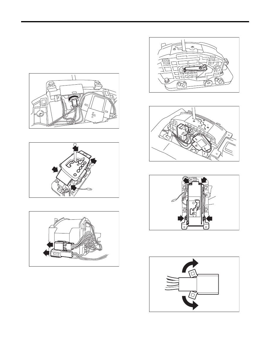
1) Remove the console box. <Ref. to EI-54, RE-
MOVAL, Console Box.>
2) Disconnect the connector.
3) Remove the indicator bulb.
4) Remove the grip.
5) Remove the indicator cover.
6) Disconnect the connector from the guide plate
upper.
7) Shift the select lever to the “N” range, and then
remove the detent spring.
8) Remove the switch assembly and shift lock sole-
noid assembly.
9) Remove the bolts, then remove the guide plate
upper from the plate lower.
10) Raise the claw of the connector.
CS-00521
CS-00522
CS-00525
(A) Guide plate upper
(B) Plate lower
CS-00538
CS-00536
CS-00524
(A)
(B)
CS-00292
CS-36
AT Shift Lock Solenoid and “P” Range Switch
CONTROL SYSTEMS
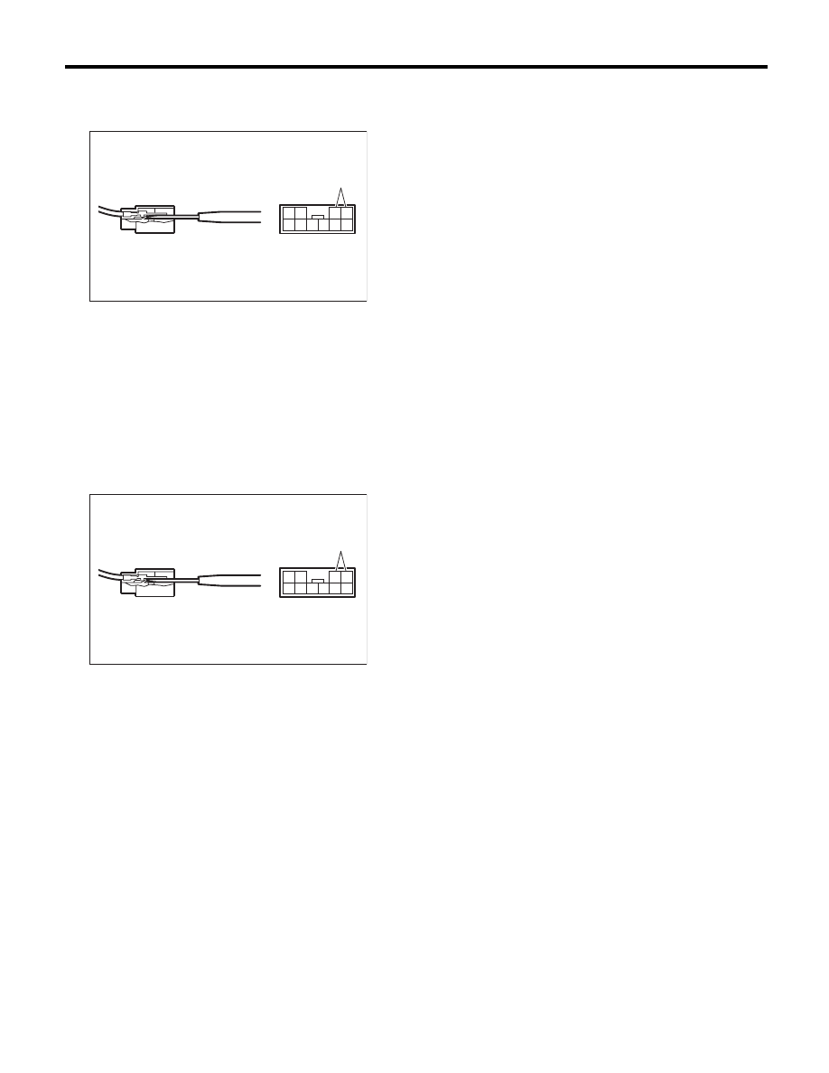
11) Disconnect the terminal of the “P” range switch
from connector, using a flat tip screwdriver with a
thin tip.
B: INSTALLATION
Install in the reverse order of removal.
NOTE:
• Refer to “COMPONENT” for each tightening
torque. <Ref. to CS-3, AT SELECT LEVER, COM-
PONENT, General Description.>
• Connect the “P” range switch terminal to connec-
tor.
(A) “P” range switch
(A) “P” range switch
CS-00529
4
10
3
9 8 7
2 1
6 5
(A)
CS-00529
4
10
3
9 8 7
2 1
6 5
(A)

CS-37
AT Shift Lock Solenoid and “P” Range Switch
CONTROL SYSTEMS
C: INSPECTION
Step
Check
Yes
No
1
CHECK SHIFT LOCK SOLENOID.
Measure the resistance of shift lock solenoid
connector terminals.
Terminals
No. 4 — No. 3:
Is the resistance 19.8 — 24.2
:? Go to step 2.
Replace the shift
lock solenoid.
2
CHECK SHIFT LOCK SOLENOID.
Connect the battery to shift lock solenoid con-
nector terminal, and then operate the solenoid.
Terminals
No. 3 (+) — No. 4 (–):
Does the shift lock solenoid
operate normally?
Go to step 3.
Replace the shift
lock solenoid.
3
CHECK “P” RANGE SWITCH.
1) Move the select lever to “P” range.
2) Measure the resistance between “P” range
switch connector terminals.
Terminals
No. 1 — No. 2:
Is the resistance less than 1
:? Go to step 4.
Replace the “P”
range switch.
4
CHECK “P” RANGE SWITCH.
1) Set the select lever to a range other than the
“P” range.
2) Measure the resistance between “P” range
switch connector terminals.
Terminals
No. 1 — No. 2:
Is the resistance 1 M
: or
more?
Normal operation
Replace the “P”
range switch.
CS-38
Body Integrated Unit
CONTROL SYSTEMS
7. Body Integrated Unit
A: NOTE
Refer to “Body Integrated Unit” for removal and in-
stallation procedure. <Ref. to SL-56, Body Integrat-
ed Unit.>
Нет комментариевНе стесняйтесь поделиться с нами вашим ценным мнением.
Текст