Subaru Legacy IV (2008 year). Service manual — part 345
EN(H4DOTC)(diag)-201
Diagnostic Procedure with Diagnostic Trouble Code (DTC)
ENGINE (DIAGNOSTICS)
Step
Check
Yes
No
1
CHECK HARNESS BETWEEN ECM AND
SECONDARY AIR COMBINATION VALVE
RELAY 1.
1) Turn the ignition switch to OFF.
2) Disconnect the connector from ECM and
secondary air combination valve relay 1.
3) Measure the voltage between ECM and
chassis ground.
Connector & terminal
(B136) No. 30 (+) — Chassis ground (–):
Is the voltage 10 V or more?
Repair the short
circuit to power in
the harness
between ECM and
secondary air com-
bination valve relay
1.
Repair the poor
contact of ECM
connector.
EN(H4DOTC)(diag)-202
Diagnostic Procedure with Diagnostic Trouble Code (DTC)
ENGINE (DIAGNOSTICS)
BG:DTC P0416 SECONDARY AIR INJECTION SYSTEM SWITCHING VALVE “B“
CIRCUIT OPEN
DTC DETECTING CONDITION:
• Immediately at fault recognition
• GENERAL DESCRIPTION <Ref. to GD(H4DOTC)-103, DTC P0416 SECONDARY AIR INJECTION SYS-
TEM SWITCHING VALVE “B“ CIRCUIT OPEN, Diagnostic Trouble Code (DTC) Detecting Criteria.>
CAUTION:
After repair or replacement of faulty parts, perform Clear Memory Mode <Ref. to EN(H4DOTC)(diag)-
52, OPERATION, Clear Memory Mode.>, and Inspection Mode <Ref. to EN(H4DOTC)(diag)-43, PRO-
CEDURE, Inspection Mode.>.
EN(H4DOTC)(diag)-203
Diagnostic Procedure with Diagnostic Trouble Code (DTC)
ENGINE (DIAGNOSTICS)
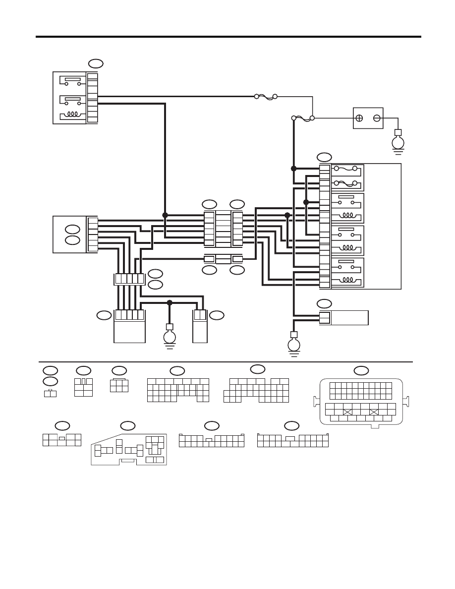
WIRING DIAGRAM:
EN-05678
B47
1
2
4
6
3
5
SBF-7
E
F9
13
12
11
14
1
2
2
1
3
4
16
15
5
6
B143
F37
B144
B21
E2
E41
E40
B134
A:
B136
C:
F37
F11
B21
E40
B47
B144
F9
B143
F37
E41
1 2 3 4
12 13 14 15
5 6 7 8
16 17 18 19
9 10 11
20 21 22
23 24 25 26 27 28 29 30 31 32 33
35
34
37
36
39
38
41
40
43
42
44
45
47
46
49
48
51
50
53
52
54
MAIN
SBF
10A
60A
9
10
8
7
E
E
11
5
20
8
C30
C19
C8
A19
A27
A29
6
1
28
47
3
2
1
6
4
1
2
9
2
16
18
14
12
10
4
14
4
F11
1 2
3
4
1
2
5
6
1
3
4 5 6
2
B134
5
6
7
8
2
1
9
4
3
10
24
22 23
25
11 12 13 14 15
26 27
28
16 17
18 19 20 21
33 34
29
32
30 31
16
10 11 12 13 14 15
25
24
30
9
8
7
17 18 19 20
28
21 22 23
29
32
31
1
2
3
4
5
6
27
26
33 34 35
B136
1
5
7
6
2
8
3
4
9
1 2 3 4
5 6 7 8 9
10 11 12 13 14
15 16 17 18 19 20
1 2 3 4
5 6 7 8 9
10 11 12 13 14 15 16 17 18 19 20
5
6
3
1
2
9
10
12
11
13
14
4
7 8
15
16
46
MAIN RELAY
BATTERY
RELAY HOLDER
SECONDARY
AIR
COMBINATION
VALVE RELAY1
SECONDARY
AIR
COMBINATION
VALVE RELAY2
SECONDARY
AIR PUMP
RELAY
SECONDARY
AIR PUMP
MAIN FUSE
BOX (M/B)
ECM
SECONDARY AIR
COMBINATION VALVE RH
(WITH BUILT-IN PRESSURE SENSOR)
SECONDARY AIR
COMBINATION
VALVE LH
EN(H4DOTC)(diag)-204
Diagnostic Procedure with Diagnostic Trouble Code (DTC)
ENGINE (DIAGNOSTICS)
Step
Check
Yes
No
1
CHECK HARNESS BETWEEN ECM AND
SECONDARY AIR COMBINATION VALVE
RELAY 2.
1) Turn the ignition switch to OFF.
2) Disconnect the connector from ECM and
secondary air combination valve relay 2.
3) Measure the resistance of harness between
ECM and secondary air combination valve relay
2.
Connector & terminal
(B136) No. 19 — (F9) No. 9:
Is the resistance less than 1
:? Go to step 2.
Repair the harness
and connector.
NOTE:
In this case, repair
the following item:
• Open circuit in
harness between
ECM and second-
ary air combination
valve relay 2
• Poor contact of
coupling connector
2
CHECK HARNESS BETWEEN ECM AND
SECONDARY AIR COMBINATION VALVE
RELAY 2.
Measure the resistance between ECM and
chassis ground.
Connector & terminal
(B136) No. 19 — Chassis ground:
Is the resistance 1 M
: or
more?
Even if DTC is
detected, the cir-
cuit has returned to
a normal condition
at this time. Repro-
duce the failure,
and then perform
the diagnosis
again.
NOTE:
In this case, tem-
porary poor con-
tact of connector
may be the cause.
Repair the ground
short circuit of har-
ness between
ECM and second-
ary air combination
valve relay 2.
Нет комментариевНе стесняйтесь поделиться с нами вашим ценным мнением.
Текст