Subaru Legacy IV (2008 year). Service manual — part 807
6MT-41
Neutral Position Switch
MANUAL TRANSMISSION AND DIFFERENTIAL
10.Neutral Position Switch
A: REMOVAL
1) Remove the manual transmission assembly
from the vehicle. <Ref. to 6MT-32, REMOVAL,
Manual Transmission Assembly.>
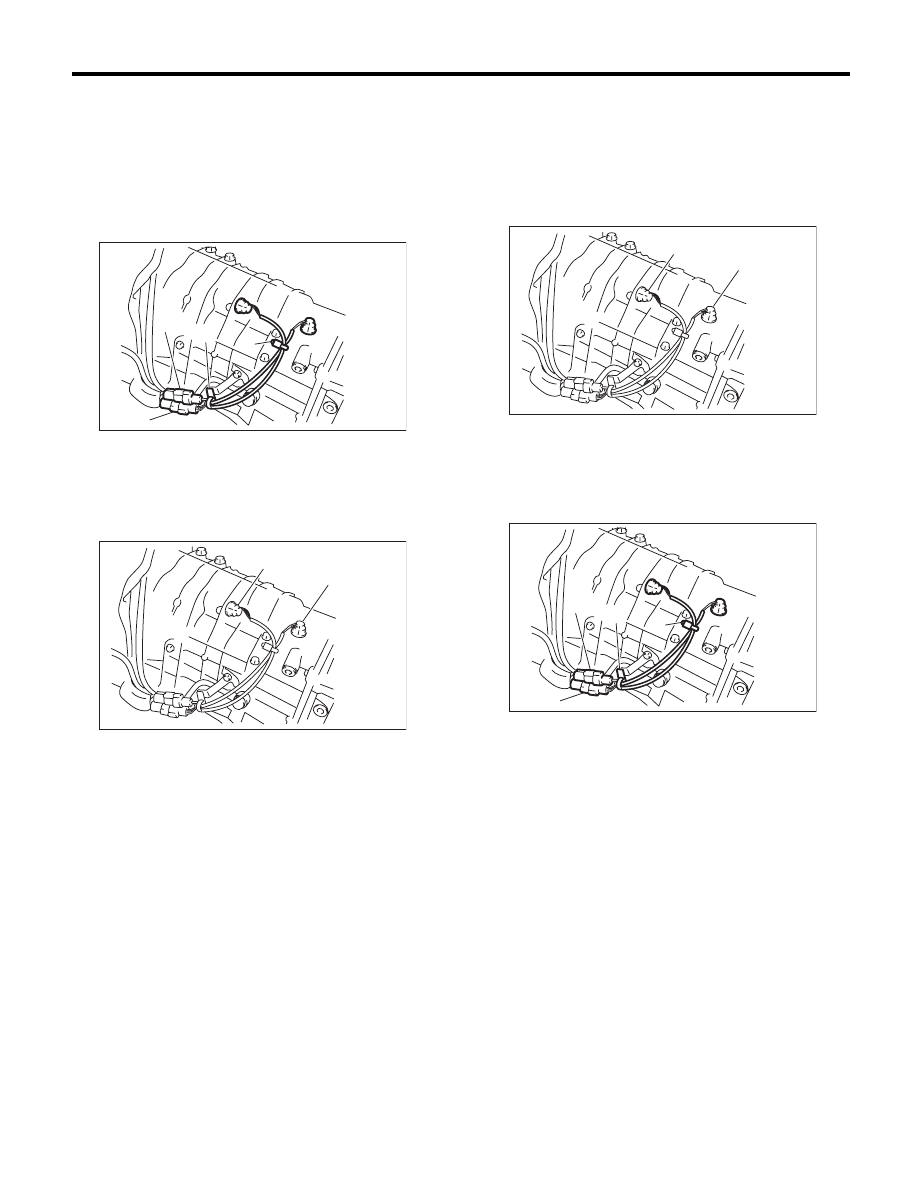
2) Disconnect the connector and clip of the neutral
position switch.
3) Remove the neutral position switch.
B: INSTALLATION
1) Install the neutral position switch.
NOTE:
Use a new gasket.
Tightening torque:
32 N·m (3.3 kgf-m, 23.6 ft-lb)
2) Connect the connector and clip of the neutral po-
sition switch.
3) Install the manual transmission assembly to the
vehicle. <Ref. to 6MT-34, INSTALLATION, Manual
Transmission Assembly.>
(A) Back-up light switch connector (Gray)
(B) Neutral position switch connector (Brown)
(C) Clip
(A) Back-up light switch
(B) Neutral position switch
MT-00471
(A)
(B)
(C)
(C)
MT-00472
(A)
(B)
(A) Back-up light switch
(B) Neutral position switch
(A) Back-up light switch connector (Gray)
(B) Neutral position switch connector (Brown)
(C) Clip
MT-00472
(A)
(B)
MT-00471
(A)
(B)
(C)
(C)
6MT-42
Neutral Position Switch
MANUAL TRANSMISSION AND DIFFERENTIAL
C: INSPECTION
1) Disconnect the ground cable from the battery.
2) Remove the intercooler. <Ref. to IN(H4DOTC)-
12, REMOVAL, Intercooler.>
3) Disconnect the transmission harness and chas-
sis harness.
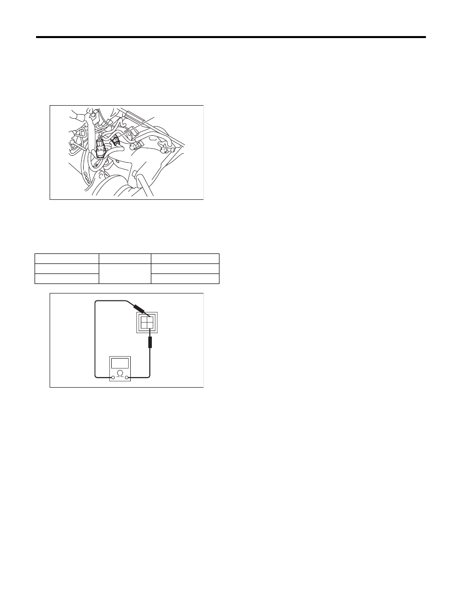
4) Measure the resistance between neutral posi-
tion switch terminals. If not within the standard val-
ues, replace the neutral position switch.
(A) Transmission connector
Gear shift position
Terminal No.
Standard
Neutral position
1 and 3
1 M
: or more
Other positions
Less than 1
:
MT-01812
(A)
MT-01089
1
2
3
4
6MT-43
Extension Case
MANUAL TRANSMISSION AND DIFFERENTIAL
11.Extension Case
A: REMOVAL
1) Remove the manual transmission assembly
from the vehicle. <Ref. to 6MT-32, REMOVAL,
Manual Transmission Assembly.>
2) Prepare the transmission for overhaul. <Ref. to
6MT-37, Preparation for Overhaul.>
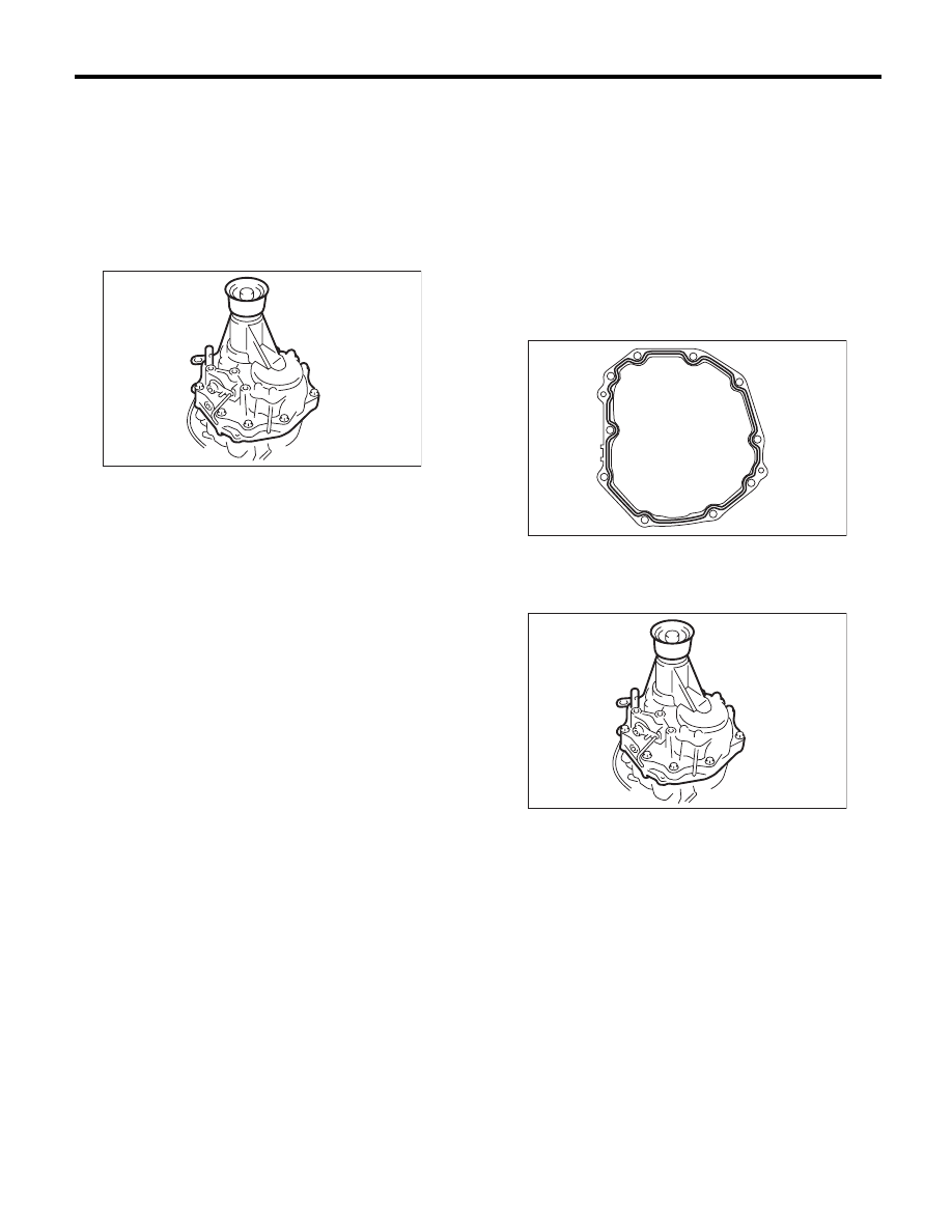
3) Remove the extension case.
4) Remove any remaining liquid gasket from the
extension case and transmission case.
B: INSTALLATION
1) Select the thrust washer of the transfer driven
gear, and attach to the extension case. <Ref. to
6MT-46, ADJUSTMENT, Extension Case.>
2) Apply a thin coat of oil to the outer surface of the
bearing cone, and attach to the extension case.
3) Select the thrust washer of the transfer drive
gear, and attach to the center differential.
4) Apply liquid gasket to the transmission case.
Liquid gasket:
THREE BOND 1215 (Part No. 004403007) or
equivalent
5) Install the extension case.
Tightening torque:
48 N·m (4.9 kgf-m, 35.4 ft-lb)
6) Install the manual transmission assembly to the
vehicle. <Ref. to 6MT-34, INSTALLATION, Manual
Transmission Assembly.>
MT-00475
MT-00476
MT-00475
6MT-44
Extension Case
MANUAL TRANSMISSION AND DIFFERENTIAL
C: DISASSEMBLY
1) Remove the transfer drive gear. <Ref. to 6MT-
53, REMOVAL, Transfer Drive Gear.>
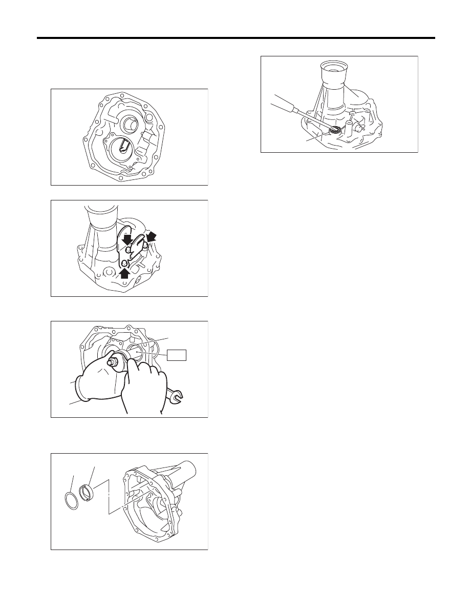
2) Remove the oil guide.
3) Remove the shift bracket.
4) Remove the bearing cone using the ST.
ST
18758AA000
PULLER
5) Remove the thrust washer and oil plate.
6) Remove the shifter arm oil seal.
7) Remove the reverse check system. <Ref. to
6MT-50, REMOVAL, Reverse Check System.>
8) Remove the extension oil seal. <Ref. to 6MT-28,
REPLACEMENT, Oil Seal.>
(A) Bearing cone
(A) Thrust washer
(B) Oil plate
MT-00477
MT-00478
MT-00479
(A)
ST
MT-00480
(A)
(B)
(A) Oil seal
MT-00481
(A)
Нет комментариевНе стесняйтесь поделиться с нами вашим ценным мнением.
Текст