Subaru Legacy IV (2008 year). Service manual — part 728

5AT-36
Line Pressure Test
AUTOMATIC TRANSMISSION
7) Perform the line pressure test.
NOTE:
• Do not perform the line pressure test for 5 sec-
onds or more at a time. Doing so will make the en-
gine oil and ATF deteriorate and the clutch and
brake to be adversely affected.
• After performing the line pressure test, be sure to
cool down the engine for at least one minute with
the select lever set in “P” or “N” range and with the
idle speed at 1,200 rpm or less.
• Fully open or fully close the throttle valve angle in
order to match the “P/L Solenoid Pressure” dis-
played on the Subaru Select Monitor.
8) Remove the ST and install the test plug.
Tightening torque:
13 N·m (1.3 kgf-m, 9.6 ft-lb)
Range of the select
lever
Throttle valve
angle
ATF temperature
condition
“P/L Solenoid Pressure” displayed
on the Subaru Select Monitor
kPa
Standard line pressure
kPa (kg/cm
2
, psi)
2nd gear of manual
mode
Full closed
45 — 55°C
(113 — 131°F)
500 — 700
Target pressure –10 — +190
(Target pressure –0.10 — +1.94,
Target pressure –1.45 — +27.5)
Full open
2,150
1,320 — 1,520
(13.46 — 15.50, 191.4 — 220.4)
R
Full closed
2,150
1,660 — 1,860
(16.93 — 18.97, 240.7 — 269.7)
5AT-37
Transfer Clutch Pressure Test
AUTOMATIC TRANSMISSION
8. Transfer Clutch Pressure
Test
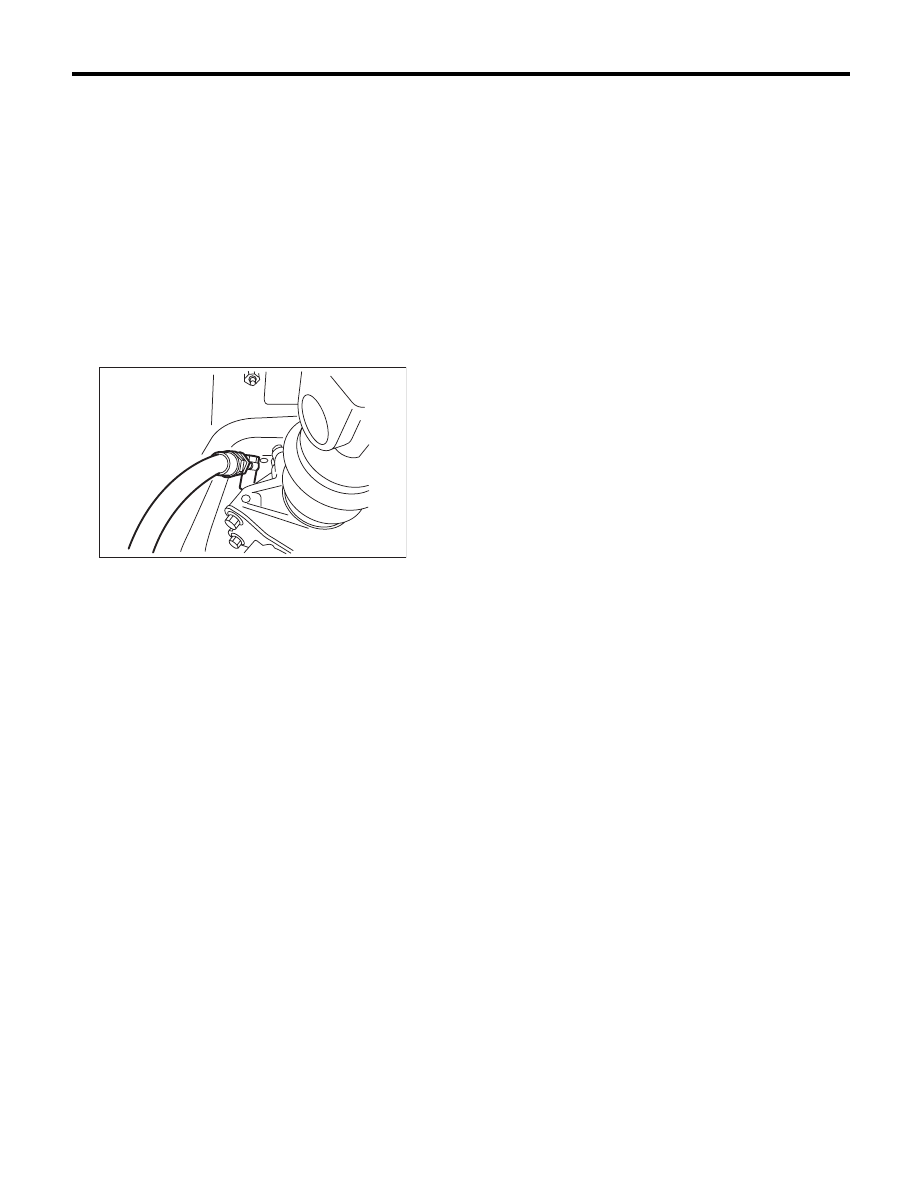
A: INSPECTION
1) Lift up the vehicle.
2) Remove the bolts holding the heat shield cover,
and move the heat shield cover to the rear.
3) Remove the test plug and attach the ST.
CAUTION:
Be careful not to cut yourself on the heat shield
cover when removing the test plugs and setting
the ST.
ST
498897800
OIL PRESSURE ADAPTER
SET
4) Set the ST.
ST
498575400
OIL PRESSURE GAUGE
ASSY
5) Lower the vehicle, and pull ST, which were set in
step 4), into the vehicle.
6) Connect the Subaru Select Monitor to the data
link connector and read the current data. <Ref. to
5AT(diag)-18, READ CURRENT DATA, OPERA-
TION, Subaru Select Monitor.>
AT-03275

5AT-38
Transfer Clutch Pressure Test
AUTOMATIC TRANSMISSION
7) Perform the transfer clutch pressure test.
NOTE:
• Do not perform the transfer clutch pressure test
for 5 seconds or more at a time. Doing so will make
the engine oil and ATF deteriorate and the clutch
and brake to be adversely affected.
• After performing the transfer clutch pressure
test, be sure to cool down the engine for at least
one minute with the select lever set in the “P” or “N”
range, and at an idle speed of 1,200 rpm or less.
• Adjust the throttle valve angle in order to obtain
the “T/F Solenoid Pressure” displayed on the Sub-
aru Select Monitor.
8) Remove the ST and install the test plug.
Tightening torque:
13 N·m (1.3 kgf-m, 9.6 ft-lb)
9) Install the heat shield cover.
Range of the select
lever
Throttle valve
angle
ATF temperature
condition
“T/F Solenoid Pressure” displayed
on the Subaru Select Monitor
kPa
Standard transfer clutch pressure
kPa (kg/cm
2
, psi)
2nd gear of manual
mode
Full open
45 — 55°C
(113 — 131°F)
1,200
990 — 1,190
(10.09 — 12.13, 143.5 — 172.5)
Partial throttle
500
400 — 600
(4.08 — 6.12, 58.0 — 87.0)
N
Full closed
0
0 — 50
(0 — 0.51, 0 — 7.3)
5AT-39
Automatic Transmission Assembly
AUTOMATIC TRANSMISSION
9. Automatic Transmission
Assembly
A: REMOVAL
1) Set the vehicle on a lift.
2) Open the front hood and support with the hood
stay.
3) Disconnect the ground cable from battery.
4) Remove the collector cover.
5) Remove the intercooler. (Turbo model)
<Ref. to IN(H4DOTC)-12, REMOVAL, Intercool-
er.>
6) Remove the air intake chamber and intake boot.
(Non-turbo model) <Ref. to IN(H6DO)-7, REMOV-
AL, Air Intake Chamber.>
7) Remove the air breather hose. <Ref. to 5AT-65,
REMOVAL, Air Breather Hose.>
8) Remove the starter. <Ref. to SC(H4SO)-6, RE-
MOVAL, Starter.>
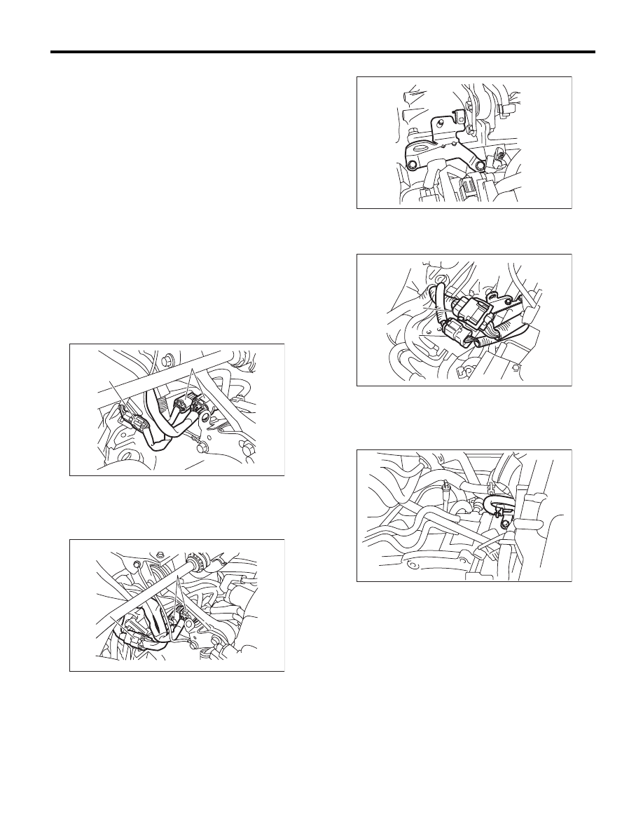
9) Disconnect the following connectors.
• Turbo model
• Non-turbo model
10) Remove the engine hanger. (Turbo model)
11) Disconnect the engine harness connectors,
and then remove the engine hanger rear. (Non-tur-
bo model)
12) Remove the water by-pass pipe. (Turbo model)
(1) Rear oxygen sensor connector
(2) Transmission harness connectors
(1) Front oxygen (A/F) and rear oxygen sensor
connector
(2) Transmission harness connectors
AT-04406
(1)
(2)
(2)
(2)
AT-04383
(2)
(2)
(2)
(1)
(1)
(1)
(A) Engine harness connectors
(B) Engine hanger rear
AT-04407
(B)
(A)
(A)
AT-02023
AT-01366
Нет комментариевНе стесняйтесь поделиться с нами вашим ценным мнением.
Текст