Subaru Legacy IV (2008 year). Service manual — part 311
EN(H4DOTC)(diag)-65
Malfunction Indicator Light
ENGINE (DIAGNOSTICS)
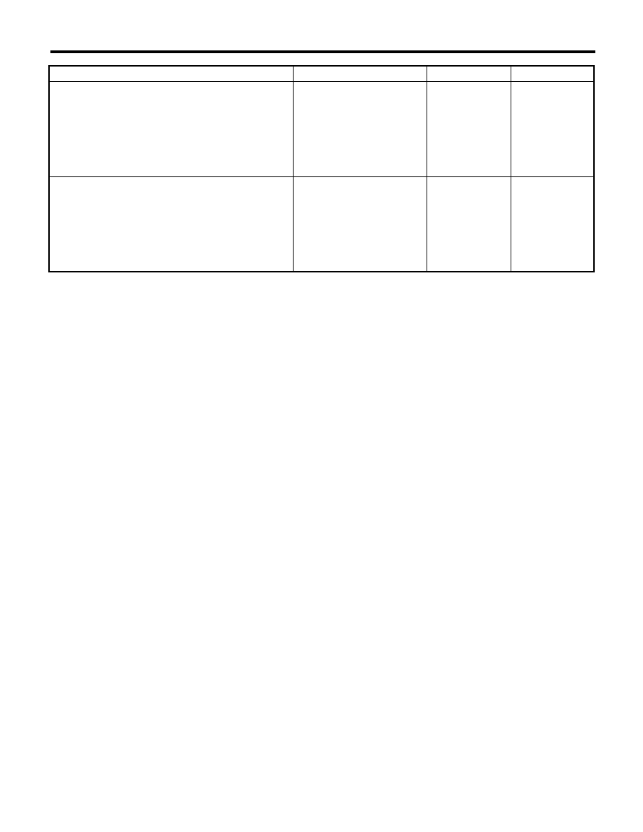
Step
Check
Yes
No
1
CHECK DELIVERY (TEST) MODE CONNEC-
TOR.
1) Disconnect the delivery (test) mode connec-
tor.
2) Turn the ignition switch to ON.
Does the malfunction indicator
light blink?
Go to step 2.
System is normal.
NOTE:
Malfunction indica-
tor light blinks
when delivery
(test) mode con-
nector is connect-
ed.
2
CHECK HARNESS BETWEEN ECM AND
CHASSIS GROUND TERMINAL.
1) Turn the ignition switch to OFF.
2) Disconnect the connectors from ECM.
3) Measure the resistance of harness between
ECM and chassis ground.
Connector & terminal
(B135) No. 27 — Chassis ground:
Is the resistance less than 5
:? Repair the short
circuit of harness
between ECM and
delivery (test)
mode connector.
Replace the ECM.
<Ref. to
FU(H4DOTC)-52,
Engine Control
Module (ECM).>
EN(H4DOTC)(diag)-66
Diagnostics for Engine Starting Failure
ENGINE (DIAGNOSTICS)
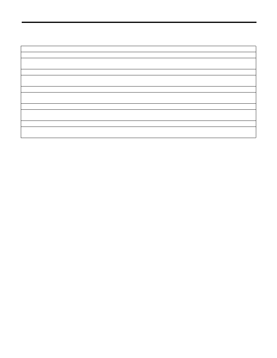
17.Diagnostics for Engine Starting Failure
A: PROCEDURE
1. Check of the fuel amount
p
2. Inspection of starter motor circuit. <Ref. to EN(H4DOTC)(diag)-67, STARTER MOTOR CIRCUIT, Diagnostics for Engine Start-
ing Failure.>
p
3. Inspection of ECM power supply and ground line. <Ref. to EN(H4DOTC)(diag)-71, CHECK POWER SUPPLY AND GROUND
LINE OF ENGINE CONTROL MODULE (ECM), Diagnostics for Engine Starting Failure.>
p
4. Inspection of ignition control system. <Ref. to EN(H4DOTC)(diag)-73, IGNITION CONTROL SYSTEM, Diagnostics for Engine
Starting Failure.>
p
5. Inspection of fuel pump circuit. <Ref. to EN(H4DOTC)(diag)-76, FUEL PUMP CIRCUIT, Diagnostics for Engine Starting Fail-
ure.>
p
6. Inspection of fuel injector circuit. <Ref. to EN(H4DOTC)(diag)-77, FUEL INJECTOR CIRCUIT, Diagnostics for Engine Starting
Failure.>
EN(H4DOTC)(diag)-67
Diagnostics for Engine Starting Failure
ENGINE (DIAGNOSTICS)
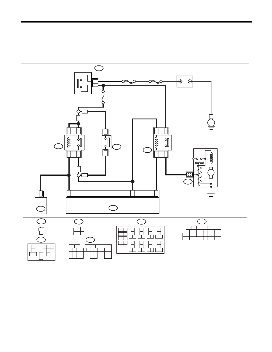
B: STARTER MOTOR CIRCUIT
CAUTION:
After repair or replacement of faulty parts, perform Clear Memory Mode <Ref. to EN(H4DOTC)(diag)-
52, OPERATION, Clear Memory Mode.>, and Inspection Mode <Ref. to EN(H4DOTC)(diag)-43, PRO-
CEDURE, Inspection Mode.>.
WIRING DIAGRAM:
31
32
20
No. 21
B225
MAIN SBF
SBF-6
E
15
13
16
14
B136
B72
B14
M
2
3
B72
1
3
4 5 6
2
AT
AT
CLUTCH
START
SWITCH
21
B106
B106
1
2
ECM
BATTERY
IGNITION
SWITCH
STARTER
RELAY
B226
9
7
10
11
INHIBITOR
RELAY
STARTER MOTOR
B136
16
10 11 12 13 14 15
25
24
30
9
8
7
17 18 19 20
28
21 22 23
29
32
31
1
2
3
4
5
6
27
26
33 34 35
MT
MT
EN-06951
11
B55
TCM
B225
13
14
15 16
17
27
24
25
26
20
21
22
23
29
30
31
28
32
35
33
34
37
38
39
36
40
8
9
10
11 12
1
2
5
3
4
7
6
19
18
B226
2
3
1
7 8 9
4
6
5
11
10
B55
5
6
7
2
1
3
4
29
10 11 12 13 14 15
25
24
16
30
9
8
17 18 19
20
28
21 22 23
32
31
26 27
33
34 35

EN(H4DOTC)(diag)-68
Diagnostics for Engine Starting Failure
ENGINE (DIAGNOSTICS)
Step
Check
Yes
No
1
CHECK BATTERY.
Check the battery voltage.
Is the voltage 12 V or more?
Go to step 2.
Charge or replace
the battery.
2
CHECK OPERATION OF STARTER MOTOR. Does the starter motor oper-
ate?
Go to step 3.
Go to step 4.
3
CHECK DTC.
Is DTC displayed? <Ref. to
EN(H4DOTC)(diag)-42,
OPERATION, Read Diagnostic
Trouble Code (DTC).>
Check the appro-
priate DTC using
the “List of Diag-
nostic Trouble
Code (DTC)”.
<Ref. to
EN(H4DOTC)(diag)
-81, List of Diag-
nostic Trouble
Code (DTC).>
The circuit has
returned to a nor-
mal condition at
this time. Repro-
duce the failure,
and then perform
the diagnosis
again.
NOTE:
In this case, tem-
porary poor con-
tact of connector
may be the cause.
4
CHECK INPUT SIGNAL FOR STARTER MO-
TOR.
1) Turn the ignition switch to OFF.
2) Disconnect the connector from starter
motor.
3) On AT models, set the select lever to the “P”
range or “N” range, and on MT models, depress
the clutch pedal.
4) Turn the ignition switch to START.
5) Measure the voltage between the starter
motor connector and the engine ground.
Connector & terminal
(B14) No. 1 (+) — Engine ground (–):
Is the voltage 10 V or more?
Check the starter
motor. <Ref. to
SC(H4SO)-6,
Starter.>
Go to step 5.
5
CHECK INPUT SIGNAL FOR STARTER MO-
TOR.
1) On AT models, set the select lever to the “P”
range or “N” range, and on MT models, depress
the clutch pedal.
2) Turn the ignition switch to START.
3) Measure the voltage between starter relay
connector and chassis ground.
Connector & terminal
(B225) No. 14 (+) — Chassis ground (–):
Is the voltage 10 V or more?
Repair the open
circuit of the har-
ness between
starter relay con-
nector and starter
motor.
Go to step 6.
6
CHECK HARNESS BETWEEN BATTERY
AND IGNITION SWITCH CONNECTOR.
1) Turn the ignition switch to OFF.
2) Disconnect the connector from ignition
switch.
3) Measure the voltage between ignition
switch connector and chassis ground.
Connector & terminal
(B72) No. 3 (+) — Chassis ground (–):
Is the voltage 10 V or more?
Go to step 7.
Check the follow-
ing item and repair
if necessary.
• Blown out of fuse
• Open or ground
short circuit of har-
ness between igni-
tion switch
connector and bat-
tery
7
CHECK IGNITION SWITCH.
Measure the resistance between ignition switch
terminals after turning the ignition switch to
START position.
Terminals
No. 2 — No. 3:
Is the resistance less than 1
:? Go to step 8.
Replace the igni-
tion switch. <Ref.
to SL-49,
REPLACEMENT,
Ignition Key Lock.>
Нет комментариевНе стесняйтесь поделиться с нами вашим ценным мнением.
Текст