Subaru Legacy IV (2008 year). Service manual — part 337
EN(H4DOTC)(diag)-169
Diagnostic Procedure with Diagnostic Trouble Code (DTC)
ENGINE (DIAGNOSTICS)
AR:DTC P0246 TURBO/SUPER CHARGER WASTEGATE SOLENOID “A” HIGH
DTC DETECTING CONDITION:
• Immediately at fault recognition
• GENERAL DESCRIPTION <Ref. to GD(H4DOTC)-79, DTC P0246 TURBO/SUPER CHARGER WASTE-
GATE SOLENOID “A” HIGH, Diagnostic Trouble Code (DTC) Detecting Criteria.>
TROUBLE SYMPTOM:
Poor driving performance
CAUTION:
After repair or replacement of faulty parts, perform Clear Memory Mode <Ref. to EN(H4DOTC)(diag)-
52, OPERATION, Clear Memory Mode.>, and Inspection Mode <Ref. to EN(H4DOTC)(diag)-43, PRO-
CEDURE, Inspection Mode.>.
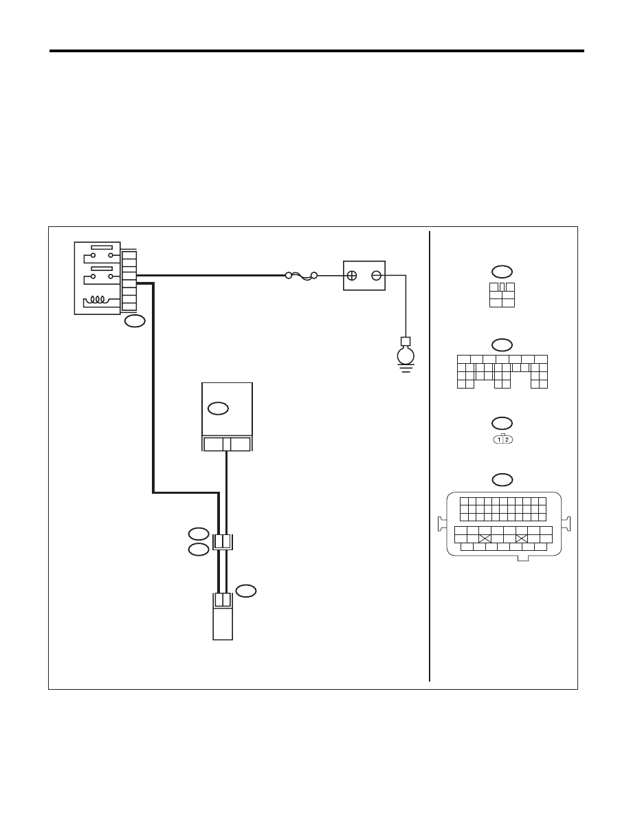
WIRING DIAGRAM:
EN-05674
1
2
7
8 9
5
6
3
4
10 11 12
19 20 21
29
30 31
13 14 15 16 17
27
28
18
22 23
24 25
26
3
4
1
2
5
6
1 2 3 4
12 13 14 15
5 6 7 8
16 17 18 19
9 10 11
20 21 22
23 24 25 26 27 28 29 30 31 32 33
35
34
37
36
39
38
41
40
43
42
44
45
47
46
49
48
51
50
53
52
54
B47
1
2
4
6
3
5
B137
E
27
SBF-7
B47
B137
E64
B21
E64
2
1
B21
E2
50
48
MAIN RELAY
BATTERY
ECM
WASTEGATE CONTROL
SOLENOID VALVE
EN(H4DOTC)(diag)-170
Diagnostic Procedure with Diagnostic Trouble Code (DTC)
ENGINE (DIAGNOSTICS)
AS:DTC P0301 CYLINDER 1 MISFIRE DETECTED
NOTE:
For the diagnostic procedure, refer to DTC P0304. <Ref. to EN(H4DOTC)(diag)-171, DTC P0304 CYLIN-
DER 4 MISFIRE DETECTED, Diagnostic Procedure with Diagnostic Trouble Code (DTC).>
AT:DTC P0302 CYLINDER 2 MISFIRE DETECTED
NOTE:
For the diagnostic procedure, refer to DTC P0304. <Ref. to EN(H4DOTC)(diag)-171, DTC P0304 CYLIN-
DER 4 MISFIRE DETECTED, Diagnostic Procedure with Diagnostic Trouble Code (DTC).>
AU:DTC P0303 CYLINDER 3 MISFIRE DETECTED
NOTE:
For the diagnostic procedure, refer to DTC P0304. <Ref. to EN(H4DOTC)(diag)-171, DTC P0304 CYLIN-
DER 4 MISFIRE DETECTED, Diagnostic Procedure with Diagnostic Trouble Code (DTC).>
Step
Check
Yes
No
1
CHECK HARNESS BETWEEN ECM AND
WASTEGATE CONTROL SOLENOID
VALVE.
1) Turn the ignition switch to OFF.
2) Disconnect the connector from ECM and
wastegate control solenoid valve.
3) Turn the ignition switch to ON.
4) Measure the voltage between ECM and
chassis ground.
Connector & terminal
(B137) No. 27 (+) — Chassis ground (–):
Is the voltage 10 V or more?
Repair short cir-
cuit of the harness
to power supply
between ECM and
wastegate control
solenoid valve con-
nector.
Go to step 2.
2
CHECK WASTEGATE CONTROL SOLE-
NOID VALVE.
1) Turn the ignition switch to OFF.
2) Measure the resistance between wastegate
control solenoid valve terminals.
Terminals
No. 1 — No. 2:
Is the resistance less than 1
:? Replace the waste-
gate control sole-
noid valve. <Ref. to
FU(H4DOTC)-45,
Wastegate Control
Solenoid Valve.>
Repair the poor
contact of ECM
connector.
EN(H4DOTC)(diag)-171
Diagnostic Procedure with Diagnostic Trouble Code (DTC)
ENGINE (DIAGNOSTICS)
AV:DTC P0304 CYLINDER 4 MISFIRE DETECTED
DTC DETECTING CONDITION:
• Two consecutive driving cycles with fault
• Immediately at fault recognition (A misfire which could damage catalyst occurs.)
• GENERAL DESCRIPTION <Ref. to GD(H4DOTC)-85, DTC P0304 CYLINDER 4 MISFIRE DETECTED,
Diagnostic Trouble Code (DTC) Detecting Criteria.>
TROUBLE SYMPTOM:
• Engine stalls.
• Improper idling
• Rough driving
CAUTION:
After repair or replacement of faulty parts, perform Clear Memory Mode <Ref. to EN(H4DOTC)(diag)-
52, OPERATION, Clear Memory Mode.>, and Inspection Mode <Ref. to EN(H4DOTC)(diag)-43, PRO-
CEDURE, Inspection Mode.>.
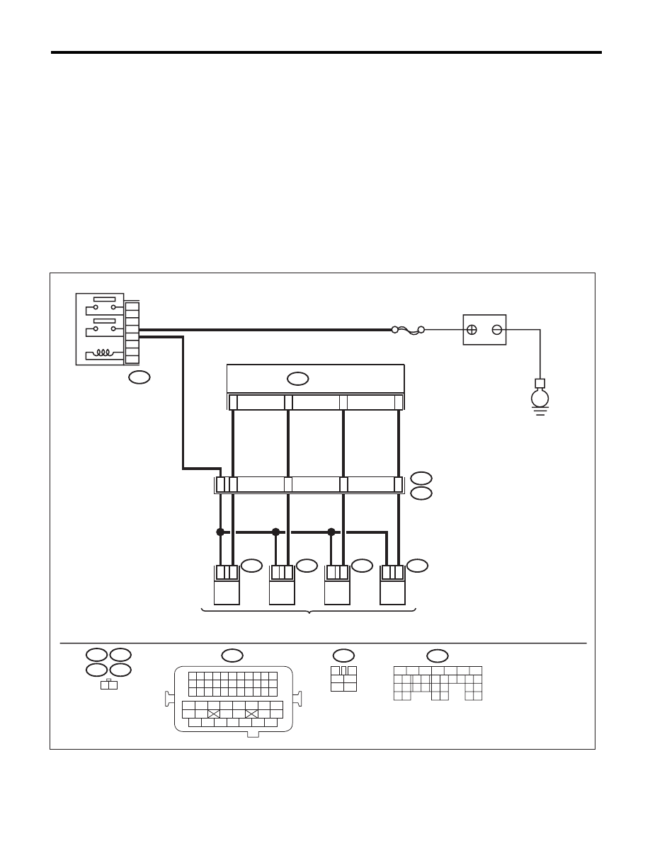
WIRING DIAGRAM:
EN-05668
E
#4
1
2
SBF-7
#3
1
2
#2
1
2
B21
#1
1
2
48
54
53
52
51
8
9
10
11
1 2
5
3
6
4
2
1
B21
B137
E5
E5
E2
E6
E6
E16
E16
E17
B47
E17
B47
3
4
1
2
5
6
B137
1 2 3 4
12 13 14 15
5 6 7 8
16 17 18 19
9 10 11
20 21 22
23 24 25 26 27 28 29 30 31 32 33
35
34
37
36
39
38
41
40
43
42
44
45
47
46
49
48
51
50
53
52
54
5
6
7
8
2
1
9
4
3
10
22 23
11 12 13 14 15
24 25
26
16 17
18 19 20 21
27
28 29
30 31
MAIN RELAY
ECM
BATTERY
FUEL INJECTOR

EN(H4DOTC)(diag)-172
Diagnostic Procedure with Diagnostic Trouble Code (DTC)
ENGINE (DIAGNOSTICS)
Step
Check
Yes
No
1
CHECK OUTPUT SIGNAL OF ECM.
1) Turn the ignition switch to ON.
2) Measure the voltage between ECM and
chassis ground on faulty cylinders.
Connector & terminal
#1 (B137) No. 8 (+) — Chassis ground (–):
#2 (B137) No. 9 (+) — Chassis ground (–):
#3 (B137) No. 10 (+) — Chassis ground (–):
#4 (B137) No. 11 (+) — Chassis ground (–):
Is the voltage 10 V or more?
Go to step 6.
Go to step 2.
2
CHECK HARNESS BETWEEN ECM AND
FUEL INJECTOR.
1) Turn the ignition switch to OFF.
2) Disconnect the connector from fuel injector
on faulty cylinders.
3) Measure the resistance between fuel injec-
tor connector and engine ground on faulty cylin-
ders.
Connector & terminal
#1 (E5) No. 1 — Engine ground:
#2 (E16) No. 1 — Engine ground:
#3 (E6) No. 1 — Engine ground:
#4 (E17) No. 1 — Engine ground:
Is the resistance 1 M
: or
more?
Go to step 3.
Repair the ground
short circuit of har-
ness between
ECM and fuel
injector.
3
CHECK HARNESS BETWEEN ECM AND
FUEL INJECTOR.
Measure the resistance of harness between
ECM and fuel injector on faulty cylinders.
Connector & terminal
#1 (B137) No. 8 — (E5) No. 1:
#2 (B137) No. 9 — (E16) No. 1:
#3 (B137) No. 10 — (E6) No. 1:
#4 (B137) No. 11 — (E17) No. 1:
Is the resistance less than 1
:? Go to step 4.
Repair the harness
and connector.
NOTE:
In this case, repair
the following item:
• Open circuit of
harness between
ECM and fuel in-
jector connector
• Poor contact of
coupling connector
4
CHECK FUEL INJECTOR.
Measure the resistance between fuel injector
terminals on faulty cylinder.
Terminals
No. 1 — No. 2:
Is the resistance between 5 —
20
:?
Go to step 5.
Replace the faulty
fuel injector. <Ref.
to FU(H4DOTC)-
38, Fuel Injector.>
5
CHECK POWER SUPPLY LINE.
1) Turn the ignition switch to ON.
2) Measure the voltage between fuel injector
and engine ground on faulty cylinders.
Connector & terminal
#1 (E5) No. 2 (+) — Engine ground (–):
#2 (E16) No. 2 (+) — Engine ground (–):
#3 (E6) No. 2 (+) — Engine ground (–):
#4 (E17) No. 2 (+) — Engine ground (–):
Is the voltage 10 V or more?
Repair the poor
contact of all con-
nectors in fuel
injector circuit.
Repair the harness
and connector.
NOTE:
In this case, repair
the following item:
• Open circuit in
harness between
the main relay and
fuel injector con-
nector on faulty
cylinders
• Poor contact of
coupling connector
• Poor contact of
main relay connec-
tor
Нет комментариевНе стесняйтесь поделиться с нами вашим ценным мнением.
Текст