Subaru Legacy IV (2008 year). Service manual — part 919
VDC-14
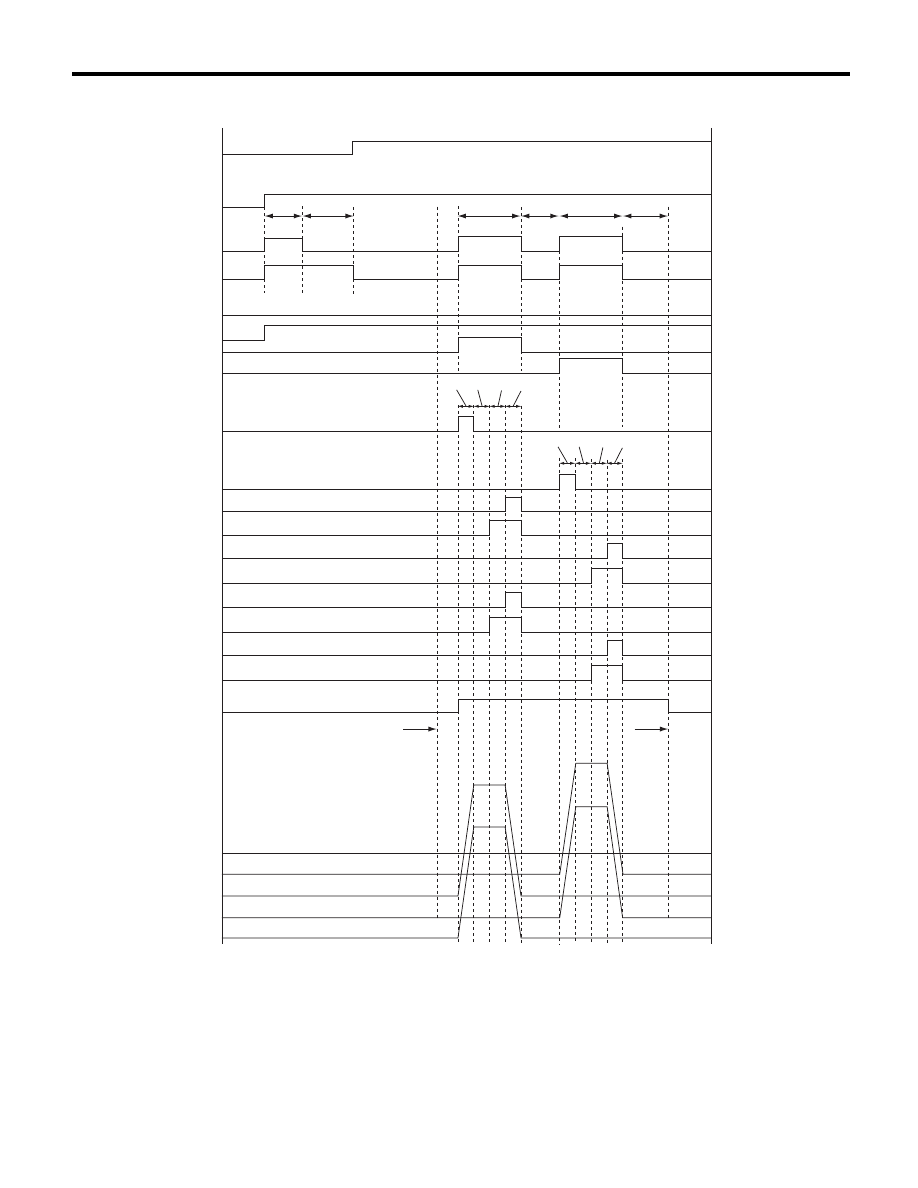
VDC Sequence Control
VEHICLE DYNAMICS CONTROL (VDC)
2. CONDITIONS FOR VDC SEQUENCE CONTROL
(20)
ON
ON
(23)
(23)
(23)
(4)
(5)
(19)
(32)
(3)
(2)
(1)
(22)
(22)
(22)
(22)
V max < 4 km/h (2.5 MPH)
V max < 10 km/h (6 MPH)
OFF
OFF
OFF
OFF
OFF
ON
VDC
(21)
(27)
(28)
(25)
(26)
(24)
(29)
(30) (31)
(25)
(24)
(8)
(7)
(9)
(10)
OFF
(11)
OFF
(12)
OFF
(14)
OFF
(15)
OFF
(16)
OFF
(13)
OFF
(18)
OFF
(17)
(6)
(33)
(35)
(34)
(36)
VDC00275
(29)
(30) (31)
(25)
VDC-15
VDC Sequence Control
VEHICLE DYNAMICS CONTROL (VDC)
NOTE:
The control operation starts from point A.
B: SPECIFICATION
1. CONDITIONS FOR COMPLETION OF
VDC SEQUENCE CONTROL
When the following conditions develop, the VDC
sequence control stops and VDC operation is re-
turned to the normal control mode.
1) When the speed of at least one wheel reaches
10 km/h (6 MPH).
2) When the brake pedal is pressed during se-
quence control and the stop light switch is set to
ON.
3) After completion of VDC sequence control.
4) When a malfunction is detected.
(1)
All wheel speed
(13)
FR decompression valve
(25)
1 second
(2)
Ignition key
(14)
FR compression valve
(26)
1.6 seconds
(3)
ABS warning light
(15)
RR decompression valve
(27)
Point A
(4)
VDC warning light
(16)
RR compression valve
(28)
Reset
(5)
Stop light switch
(17)
RL decompression valve
(29)
0.8 seconds
(6)
Valve relay
(18)
RL compression valve
(30)
1.2 seconds
(7)
VDC switching valve 1 FL
(19)
Pump motor
(31)
0.4 seconds
(8)
VDC switching valve 1 FR
(20)
1.5 seconds
(32)
Master cylinder pressure
(9)
VDC switching valve 2 FL
(21)
Approx. 3 seconds
(33)
FR wheel cylinder pressure
(10)
VDC switching valve 2 FR
(22)
Light OFF
(34)
FL wheel cylinder pressure
(11)
FL decompression valve
(23)
Light ON
(35)
RL wheel cylinder pressure
(12)
FL compression valve
(24)
3.4 seconds
(36)
RR wheel cylinder pressure
VDC-16
Yaw Rate and Lateral G Sensor
VEHICLE DYNAMICS CONTROL (VDC)
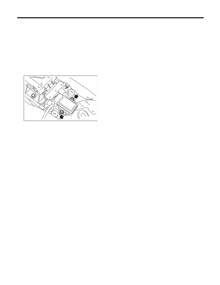
5. Yaw Rate and Lateral G Sensor
A: REMOVAL
1) Disconnect the ground cable from battery.
2) Remove the console box.
<Ref. to EI-54, Console Box.>
3) Disconnect the connector from yaw rate & lateral
G sensor.
4) Remove the yaw rate & lateral G sensor.
B: INSTALLATION
Install in the reverse order of removal.
Tightening torque:
7.5 N·m (0.76 kgf-m, 5.5 ft-lb)
CAUTION:
After completion of installation, set the follow-
ing two positions.
• Positioning to the center of steering angle
sensor
• Positioning the yaw rate & lateral G sensors
to zero
The above procedure is required for the VDC-
CM&H/U to identify the vehicle position after-
ward. For the setting procedures of the 2 steps
above, refer to “VDC Control Module and Hy-
draulic Control Unit (VDCCM&H/U)”. <Ref. to
VDC-11, ADJUSTMENT, VDC Control Module
and Hydraulic Control Unit (VDCCM&H/U).>
VDC00453

VDC-17
Yaw Rate and Lateral G Sensor
VEHICLE DYNAMICS CONTROL (VDC)
C: INSPECTION
1. YAW RATE & LATERAL G SENSOR
Step
Check
Yes
No
1
CHECK YAW RATE & LATERAL G SENSOR.
1) Turn the ignition switch to OFF.
2) Connect the Subaru Select Monitor connec-
tor to the data link connector.
3) Turn the ignition switch to ON.
4) Set the Subaru Select Monitor connector to
the {Brake Control System} mode.
5) Select {Current Data Display & Save}.
6) Read the output of the yaw rate & lateral G
sensor.
Are the indicated values as fol-
lows when the vehicle is placed
horizontally? Lateral G sensor:
–1.5 — 1.5 m/s, Yaw rate sen-
sor: –4 — 4 deg/s
Go to step 2.
Repair the harness
connector between
yaw rate & lateral
G sensor and
VDCCM&H/U. Or
replace the yaw
rate & lateral G
sensor.
2
CHECK LATERAL G SENSOR.
1) Remove the console box.
2) Remove the yaw rate & lateral G sensors
from vehicle. (Do not disconnect the connector.)
3) Read the display of Subaru Select Monitor.
NOTE:
When the yaw rate & lateral G sensor is moved
with its power supply on, DTC of yaw rate & lat-
eral G sensor may be recorded.
Is the value 6.8 — 12.8 m/s
when the yaw rate & lateral G
sensor is inclined 90° to the
right?
Go to step 3.
Repair the harness
connector between
yaw rate & lateral
G sensor and
VDCCM&H/U. Or
replace the yaw
rate & lateral G
sensor.
3
CHECK LATERAL G SENSOR.
Read the display of Subaru Select Monitor.
NOTE:
When the yaw rate & lateral G sensor is moved
with its power supply on, DTC of yaw rate & lat-
eral G sensor may be recorded.
Is the value –6.8 — –12.8 m/s
when the yaw rate & lateral G
sensor is inclined 90° to the
right?
Yaw rate & lateral
G sensors are nor-
mal.
Repair the harness
connector between
yaw rate & lateral
G sensor and
VDCCM&H/U. Or
replace the yaw
rate & lateral G
sensor.
Нет комментариевНе стесняйтесь поделиться с нами вашим ценным мнением.
Текст