Subaru Legacy IV (2008 year). Service manual — part 269
ME(H4DOTC)-56
Cam Sprocket
MECHANICAL
16.Cam Sprocket
A: REMOVAL
NOTE:
When replacing the single part, perform the work
with the engine installed to body.
1) Remove the V-belts. <Ref. to ME(H4DOTC)-41,
REMOVAL, V-belt.>
2) Remove the crank pulley. <Ref. to
ME(H4DOTC)-44, REMOVAL, Crank Pulley.>
3) Remove the timing belt cover. <Ref. to
ME(H4DOTC)-46, REMOVAL, Timing Belt Cover.>
4) Remove the timing belt. <Ref. to ME(H4DOTC)-
47, REMOVAL, Timing Belt.>
5) Remove the actuator cover of the intake cam
sprocket.
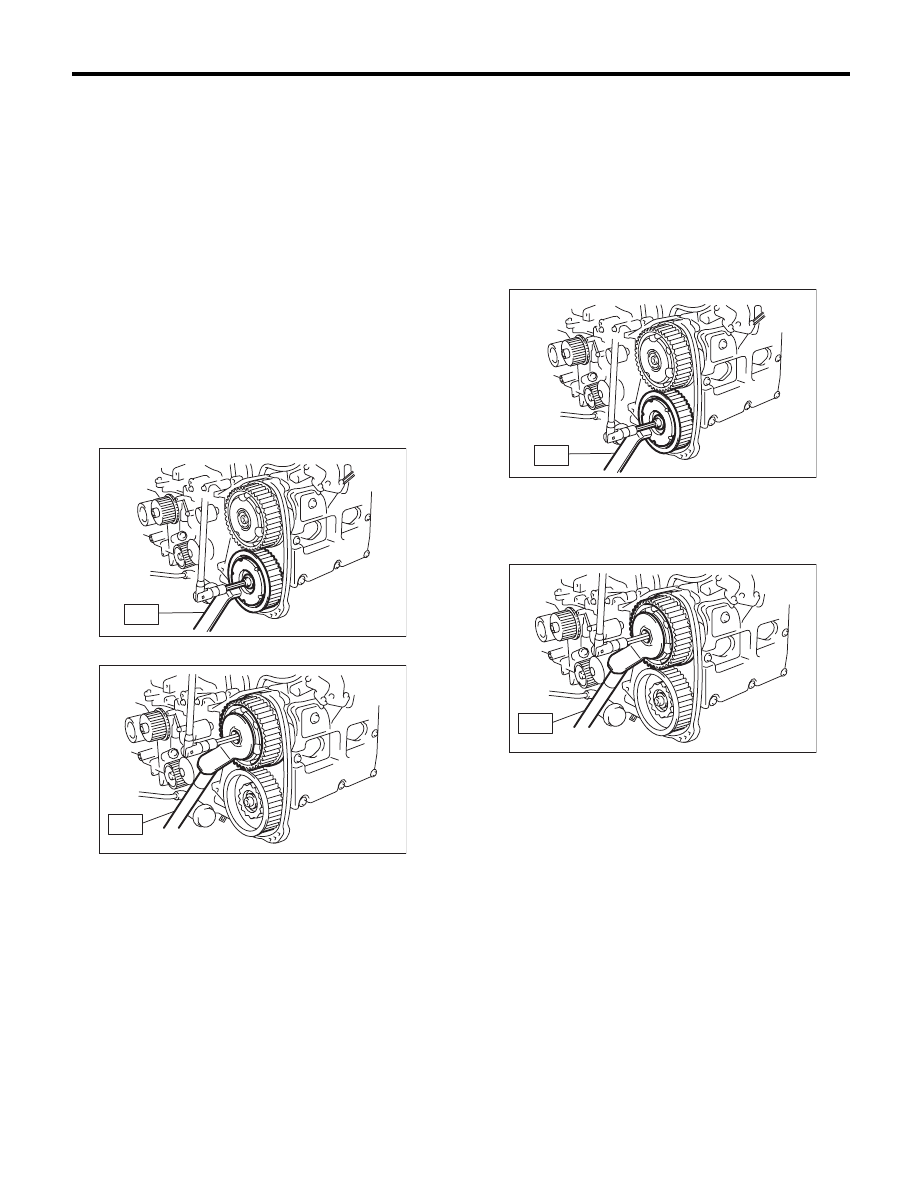
6) Fasten the cam sprocket and remove from the
cam shaft using ST.
ST
499207400
CAM SPROCKET WRENCH
ST
499977500
CAM SPROCKET WRENCH
B: INSTALLATION
1) Fasten the cam sprocket and install to the cam
shaft using ST.
NOTE:
Do not confuse the cam sprockets (LH) and (RH)
during installation.
ST
499207400
CAM SPROCKET WRENCH
Tightening torque:
Tighten to 30 N·m (3.1 kgf-m, 22.1 ft-lb) of
torque, and then tighten further by 45°.
ST
499977500
CAM SPROCKET WRENCH
Tightening torque:
Tighten to 30 N·m (3.1 kgf-m, 22.1 ft-lb) of
torque, and then tighten further by 45°.
2) Attach the actuator cover of the intake cam
sprocket.
NOTE:
Use new O-rings.
Tightening torque:
3.4 N·m (0.3 kgf-m, 2.5 ft-lb)
3) Install the timing belt. <Ref. to ME(H4DOTC)-49,
INSTALLATION, Timing Belt.>
4) Install the timing belt cover. <Ref. to ME(H4DOTC)-
46, INSTALLATION, Timing Belt Cover.>
5) Install the crank pulley. <Ref. to ME(H4DOTC)-
44, INSTALLATION, Crank Pulley.>
6) Install the V-belts. <Ref. to ME(H4DOTC)-42,
INSTALLATION, V-belt.>
C: INSPECTION
1) Check the cam sprocket teeth for abnormal wear
and scratches.
2) Make sure there is no free play between cam
sprocket and key.
ME-03282
ST
ME-03283
ST
ME-03282
ST
ME-03283
ST
ME(H4DOTC)-57
Crank Sprocket
MECHANICAL
17.Crank Sprocket
A: REMOVAL
NOTE:
When replacing the single part, perform the work
with the engine installed to body.
1) Remove the V-belts. <Ref. to ME(H4DOTC)-41,
REMOVAL, V-belt.>
2) Remove the crank pulley. <Ref. to
ME(H4DOTC)-44, REMOVAL, Crank Pulley.>
3) Remove the timing belt cover. <Ref. to
ME(H4DOTC)-46, REMOVAL, Timing Belt Cover.>
4) Remove the timing belt. <Ref. to ME(H4DOTC)-
47, REMOVAL, Timing Belt.>
5) Remove the crank sprocket.
B: INSTALLATION
1) Install the crank sprocket.
2) Install the timing belt. <Ref. to ME(H4DOTC)-49,
INSTALLATION, Timing Belt.>
3) Install the timing belt cover. <Ref. to
ME(H4DOTC)-46, INSTALLATION, Timing Belt
Cover.>
4) Install the crank pulley. <Ref. to ME(H4DOTC)-
44, INSTALLATION, Crank Pulley.>
5) Install the V-belts. <Ref. to ME(H4DOTC)-42,
INSTALLATION, V-belt.>
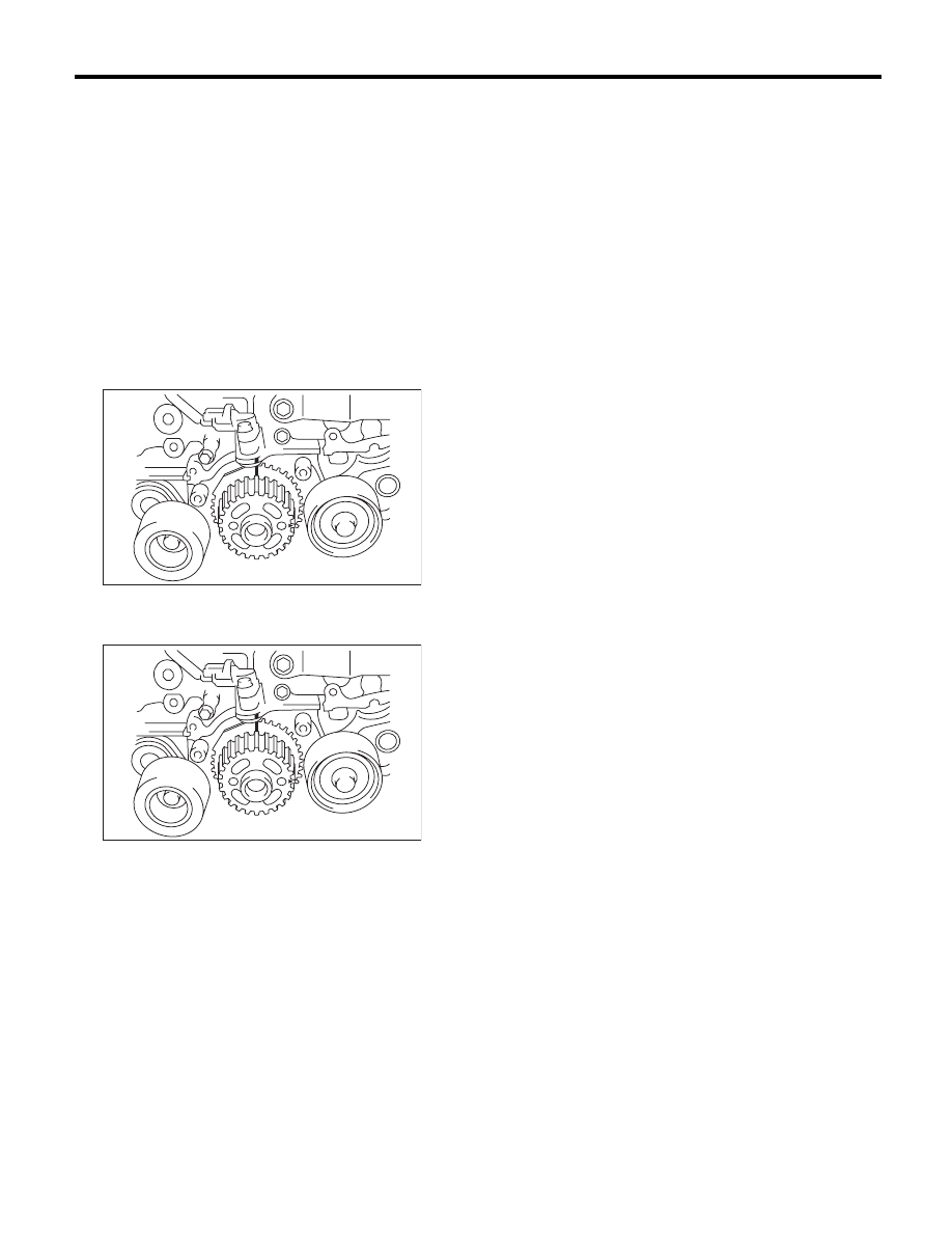
C: INSPECTION
1) Check the crank sprocket teeth for abnormal
wear and scratches.
2) Make sure there is no free play between crank
sprocket and key.
3) Check the crank sprocket protrusion used for
sensor for damage and contamination of foreign
matter.
ME-00103
ME-00103
ME(H4DOTC)-58
Camshaft
MECHANICAL
18.Camshaft
A: REMOVAL
NOTE:
When replacing the single part, perform the work
with the engine installed to body. Refer to “Valve
Clearance” for preparation procedures. <Ref. to
ME(H4DOTC)-26, INSPECTION, Valve Clear-
ance.>
1) Remove the V-belts. <Ref. to ME(H4DOTC)-41,
REMOVAL, V-belt.>
2) Remove the crank pulley. <Ref. to
ME(H4DOTC)-44, REMOVAL, Crank Pulley.>
3) Remove the timing belt cover. <Ref. to
ME(H4DOTC)-46, REMOVAL, Timing Belt Cover.>
4) Remove the timing belt. <Ref. to ME(H4DOTC)-
47, REMOVAL, Timing Belt.>
5) Remove the cam sprocket. <Ref. to
ME(H4DOTC)-56, REMOVAL, Cam Sprocket.>
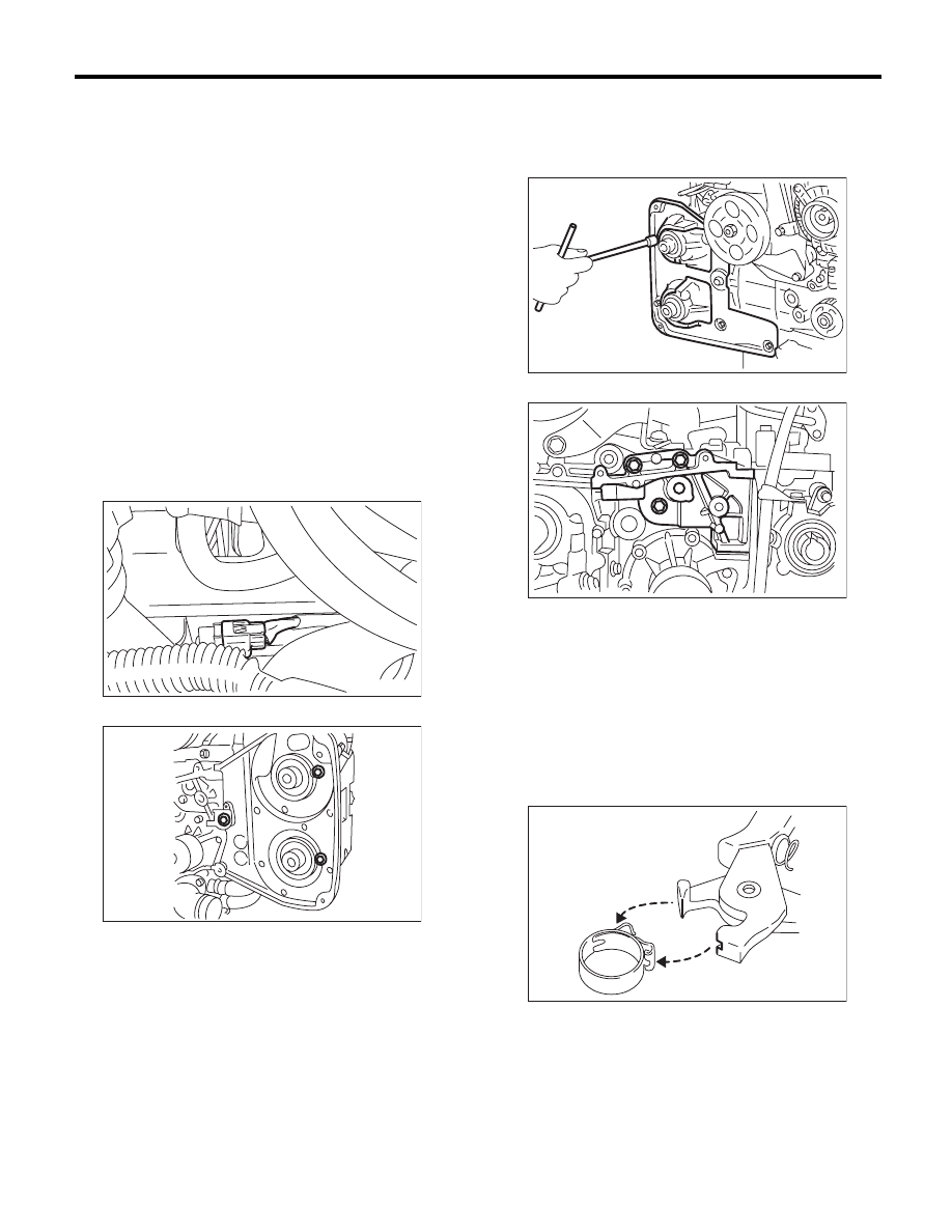
6) Disconnect the oil flow control solenoid valve as-
sembly connector.
7) Remove the timing belt cover No. 2 LH.
8) Remove the timing belt cover No. 2 RH.
NOTE:
Do not damage or lose the seal rubber when re-
moving the timing belt covers.
9) Remove the tensioner bracket.
10) Remove the ignition coil. <Ref. to
IG(H4DOTC)-7, REMOVAL, Ignition Coil.>
11) Disconnect the PCV hose from the rocker cov-
er.
NOTE:
For the PCV hose affixed with the clamp, fit the de-
pression in the ST with the protrusion of the clamp
as shown in the figure below, unlock the clamp and
disconnect.
ST
18353AA000
CLAMP PLIERS
12) Remove the rocker cover and gasket.
ME-03094
ME-00106
ME-00107
ME-00105
ME-03630
ME(H4DOTC)-59
Camshaft
MECHANICAL
13) Remove the union screw without filter (without
protrusion) which secures the oil pipe to the front
camshaft cap.
14) Loosen the front camshaft cap upper area and
intake camshaft cap bolts equally, a little at a time
in alphabetical order as shown in the figure.
15) Loosen the front camshaft cap lower area and
exhaust camshaft cap bolts equally, a little at a time
in alphabetical order as shown in the figure.
16) Remove the front camshaft cap.
17) Remove the intake camshaft caps and the in-
take camshaft.
18) Remove the exhaust camshaft caps and the
exhaust camshaft.
NOTE:
Arrange camshaft caps in order so that they can be
installed in their original positions.
19) Remove the oil seal.
CAUTION:
Do not scratch the journal surface when remov-
ing the oil seal.
20) Similarly, remove the camshaft RH and related
parts.
B: INSTALLATION
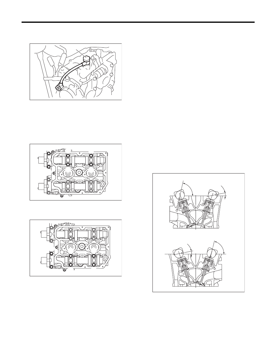
1) Install the camshaft.
Apply engine oil to the cylinder head at camshaft
journal installation location before installing the
camshaft. Install the camshaft so that each valve is
close to or in contact with base circle of the cam
lobe.
NOTE:
• Set the camshaft to the position shown in the fig-
ure.
• When set at the position shown in the figure, it is
not necessary to rotate the camshaft RH when in-
stalling the timing belt, but it is necessary to rotate
the camshaft LH slightly.
Intake camshaft LH:
Rotate 80° clockwise.
Exhaust camshaft LH:
Rotate 45° counterclockwise.
(A) Union screw with filter (with protrusion)
(B) Union screw without filter (without protrusion)
(C) Oil pipe
(A)
(B)
ME-03555
(C)
ME-00771
(A)
(E)
(F)
(B)
(D)
(C)
ME-00772
(A)
(E)
(F)
(B)
(D)
(C)
A Cylinder head LH
B Cylinder head RH
(a) Intake camshaft
(b) Exhaust camshaft
ME-00111
11
11
77.5
77.5
(a)
(b)
(a)
(b)
A
B
Нет комментариевНе стесняйтесь поделиться с нами вашим ценным мнением.
Текст