Subaru Legacy IV (2008 year). Service manual — part 1008
AB(diag)-20
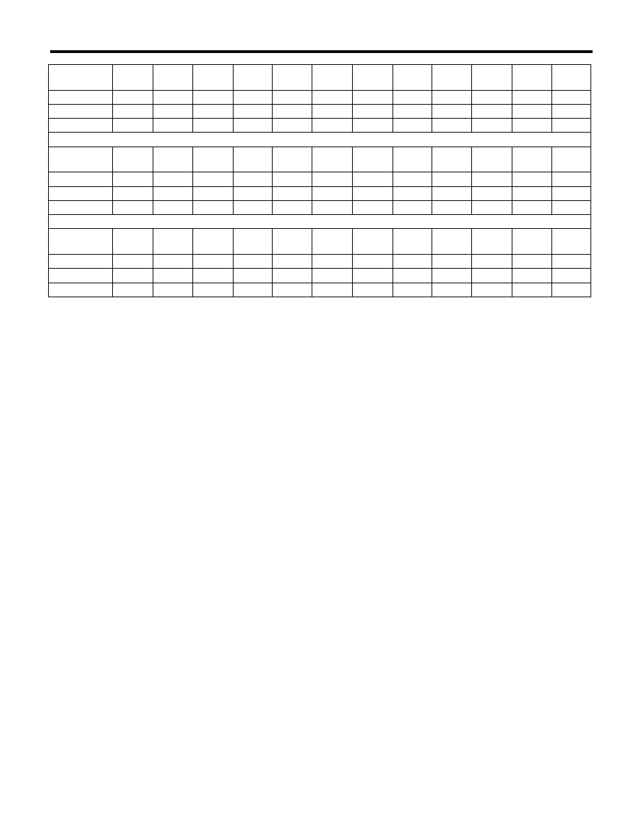
Electrical Component Location
AIRBAG SYSTEM (DIAGNOSTICS)
Connector
No.
(AB1)
(AB2)
(AB6)
(AB7)
(AB9)
(AB10)
(AB13)
(AB16)
(AB17)
(AB18)
(AB19)
(AB20)
Pin
10
4
30
4
4
4
2
2
24
24
2
2
Color
Yellow
Yellow
Yellow
Yellow
Yellow
Yellow
Yellow
Yellow
Yellow
Yellow
Yellow
Yellow
Male/Female
Female
Female
Female
Male
Female
Male
Female Female Female
Female
Female
Male
Connector
No.
(AB21)
(AB23)
(AB24)
(AB25)
(AB26)
(AB28)
(AB31)
(AB32)
(AB33)
(AB34)
(AB37)
(AB38)
Pin
2
4
2
2
2
4
2
4
2
4
2
2
Color
Black
Yellow
Yellow
Yellow
Black
Yellow
Black
Yellow
Black
Yellow
Orange
Black
Male/Female
Female
Female
Female
Male
Female
Female
Female Female Female
Female
Female Female
Connector
No.
(AB41)
(AB43)
(AB53)
(AB56)
(AB58)
(AB59)
(AB60)
(AB62)
Pin
2
18
6
3
3
6
2
3
Color
Yellow
Black
Gray
Brown
Gray
Gray
Yellow
Brown
Male/Female
Female
Female
Female
Male
Female
Male
Male
Female
AB(diag)-21
Airbag Connector
AIRBAG SYSTEM (DIAGNOSTICS)
5. Airbag Connector
A: PROCEDURE
For detailed operation procedure, refer to the “Air-
bag Connector”. <Ref. to AB-8, Airbag Connector.>
AB(diag)-22
Airbag Control Module I/O Signal
AIRBAG SYSTEM (DIAGNOSTICS)
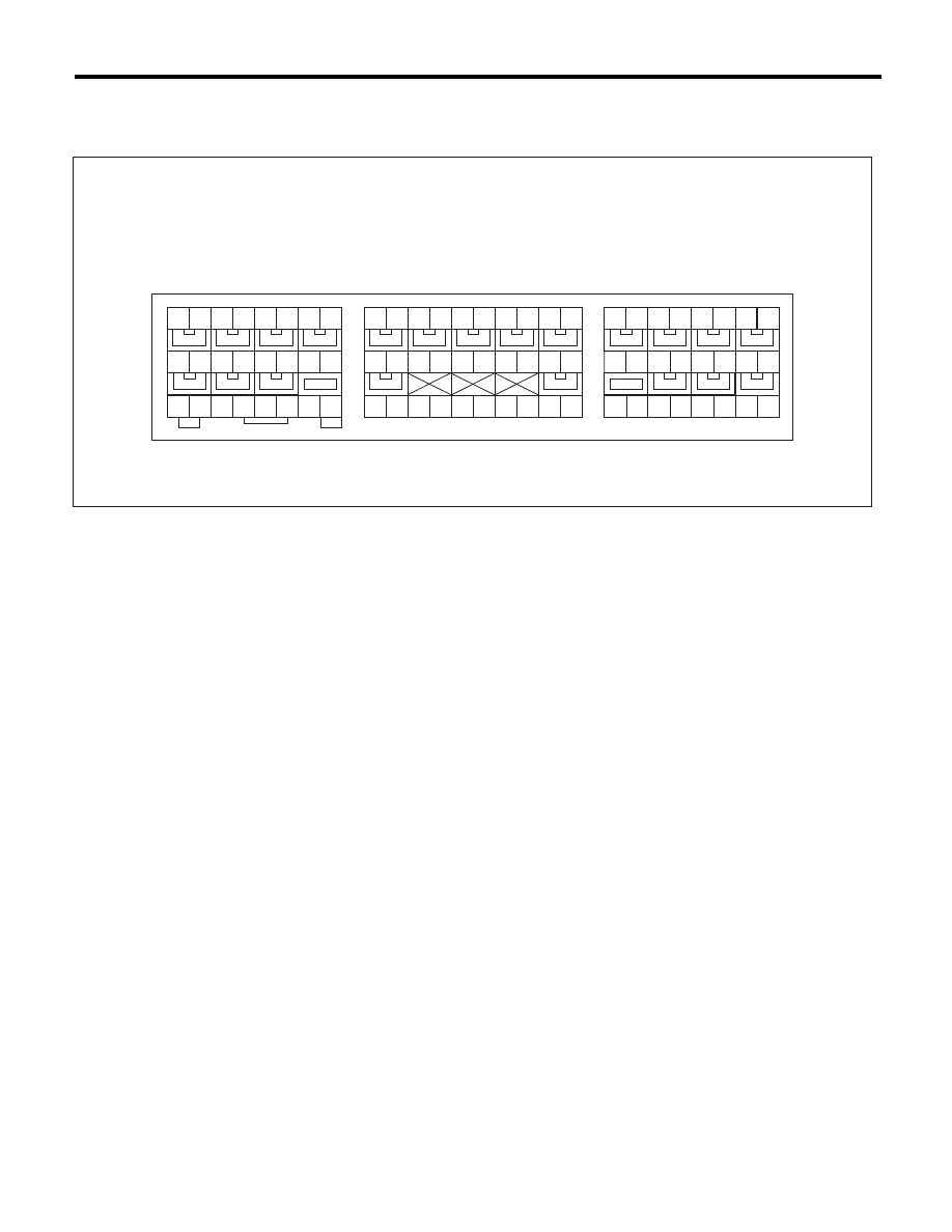
6. Airbag Control Module I/O Signal
A: ELECTRICAL SPECIFICATION
• Terminal numbers in airbag control module connector are shown in the figure.
• Airbag warning light illuminates when the connector is removed from airbag control module.
AB-01758
18
19
20
21
22
23
24
25
26
27
28
1
2
3
㧡
㧢
㧣
㧤
1
㧜 㧥
4
11
12
13
14
16
17
15
29
30
18
19
20
21
22
23
24
1
2
3
㧡
㧢
㧣
㧤
1
㧜 㧥
4
11
12
13
14
16
17
15
18
19
20
21
22
23
24
1
2
3
㧡
㧢
㧣
㧤
1
㧜 㧥
4
11
12
13
14
16
17
15
(1)
(2)
(3)

AB(diag)-23
Airbag Control Module I/O Signal
AIRBAG SYSTEM (DIAGNOSTICS)
B: WIRING DIAGRAM
Refer to the WI section wiring diagram. <Ref. to WI-121, WIRING DIAGRAM, Airbag System.>
Item
Control module terminal No.
Data link connector
(1) — 16
Combination meter
(1) — 11
Battery power supply
Dedicated fuse
(1) — 21
Passenger’s airbag module level one
+
(1) — 4
–
(1) — 3
Passenger’s airbag module level two
+
(1) — 1
–
(1) — 2
Driver’s airbag module level one
+
(1) — 5
–
(1) — 6
Driver’s airbag module level two
+
(1) — 8
–
(1) — 7
Front sub sensor LH
+
(1) — 30
–
(1) — 28
Front sub sensor RH
+
(1) — 29
–
(1) — 27
Ground line (GND)
(1) — 25
(1) — 26
Passenger’s airbag OFF indicator
(1) — 17
Passenger’s airbag ON indicator
(1) — 23
Passenger’s seat belt warning light (integrated module)
(1) — 15
Seat belt pretensioner LH
+
(2) — 5
–
(2) — 6
Side airbag sensor LH
Curtain airbag sensor LH
+
(2) — 24
–
(2) — 23
Side airbag module LH
+
(2) — 1
–
(2) — 2
Curtain airbag module LH
+
(2) — 4
–
(2) — 3
Seat belt pretensioner RH
+
(3) — 4
–
(3) — 3
Side airbag sensor RH
Curtain airbag sensor RH
+
(3) — 17
–
(3) — 18
Side airbag module RH
+
(3) — 8
–
(3) — 7
Curtain airbag module RH
+
(3) — 5
–
(3) — 6
Satellite safing sensor
+
(2) — 20
–
(2) — 21
Occupant detection control module
+
(3) — 16
–
(3) — 24
Нет комментариевНе стесняйтесь поделиться с нами вашим ценным мнением.
Текст