Subaru Legacy IV (2008 year). Service manual — part 124
EN(H4SO)(diag)-99
Diagnostic Procedure with Diagnostic Trouble Code (DTC)
ENGINE (DIAGNOSTICS)
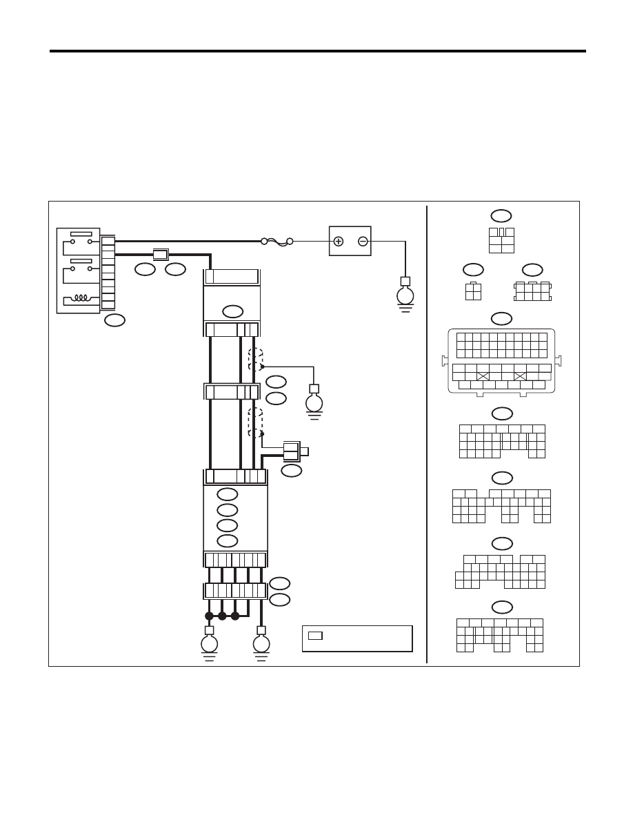
G: DTC P0038 HO2S HEATER CONTROL CIRCUIT HIGH (BANK 1 SENSOR 2)
DTC DETECTING CONDITION:
• Two consecutive driving cycles with fault
• GENERAL DESCRIPTION <Ref. to GD(H4SO)-19, DTC P0038 HO2S HEATER CONTROL CIRCUIT
HIGH (BANK 1 SENSOR 2), Diagnostic Trouble Code (DTC) Detecting Criteria.>
CAUTION:
After repair or replacement of faulty parts, perform Clear Memory Mode <Ref. to EN(H4SO)(diag)-50,
OPERATION, Clear Memory Mode.>, and Inspection Mode <Ref. to EN(H4SO)(diag)-41, PROCEDURE,
Inspection Mode.>.
WIRING DIAGRAM:
EN-06836
A5
D1
D2
D3
D7
36
34
35
37
52
ECM
B21
B138
E2
B135
B:
D: B137
C: B136
E
E
A: B134
B137
5
6
7
8
2
1
9
4
3
10
22 23
11 12 13 14 15
24 25
26
16 17
18 19 20 21
27
28 29
30 31
B134
5
6
7
8
2
1
9
4
3
10
24
22 23
25
11 12 13 14 15
26 27
28
16 17
18 19 20 21
33 34
29
32
30 31
B136
5
6
7 8
2
1
9
4
3
10
24
22 23
25
11 12 13 14 15
26 27
28
16
17 18 19 20 21
33 34
29
32
30
31
35
B135
5
6
7
8
2
1
9
4
3
10
24
22 23
25
11 12 13 14 15
26 27
28
16 17 18 19
20 21
29 30 31
32 33
34 35
A:
B:
C:
D:
*
*
3
4
1
2
5
6
B327
SBF-5
E
B327
E23
6
4
5
3
2
1
1
B21
E2
50
53
1
19
E2
B21
E
E23
BATTERY
REAR OXYGEN
SENSOR
A/F, OXYGEN
SENSOR RELAY
1
3 4
2
2
3
4
B1
B4
A29
C4
B138
3 4
5 6
1 2
7 8
B21
1 2 3 4 5 6 7 8 9 10 11
12 13 14 15 16 17 18 19 20 21 22
23 24 25 26 27 28 29 30 31 32 33
34
35
42
43
36
37
38
39
48
49
50
51
52
53
54
40
41
44
45
46
47
: TERMINAL No. OPTIONAL
ARRANGEMENT
*

EN(H4SO)(diag)-100
Diagnostic Procedure with Diagnostic Trouble Code (DTC)
ENGINE (DIAGNOSTICS)
Step
Check
Yes
No
1
CHECK HARNESS BETWEEN ECM AND
REAR OXYGEN SENSOR.
1) Turn the ignition switch to OFF.
2) Measure the voltage between ECM and
chassis ground.
Connector & terminal
(B136) No. 4 (+) — Chassis ground (–):
Is the voltage 10 V or more?
Repair the short
circuit to power in
the harness
between ECM and
rear oxygen sensor
connector.
Go to step 2.
2
CHECK GROUND CIRCUIT FOR ECM.
1) Disconnect the connectors from ECM.
2) Measure the resistance between ECM and
chassis ground.
Connector & terminal
(B134) No. 5 — Chassis ground:
(B137) No. 1 — Chassis ground:
(B137) No. 2 — Chassis ground:
(B137) No. 3 — Chassis ground:
(B137) No. 7 — Chassis ground:
Is the resistance less than 5
:? Repair the poor
contact of ECM
connector.
Repair the harness
and connector.
NOTE:
In this case, repair
the following item:
• Open circuit of
harness between
ECM and engine
ground
• Poor contact of
coupling connector
EN(H4SO)(diag)-101
Diagnostic Procedure with Diagnostic Trouble Code (DTC)
ENGINE (DIAGNOSTICS)
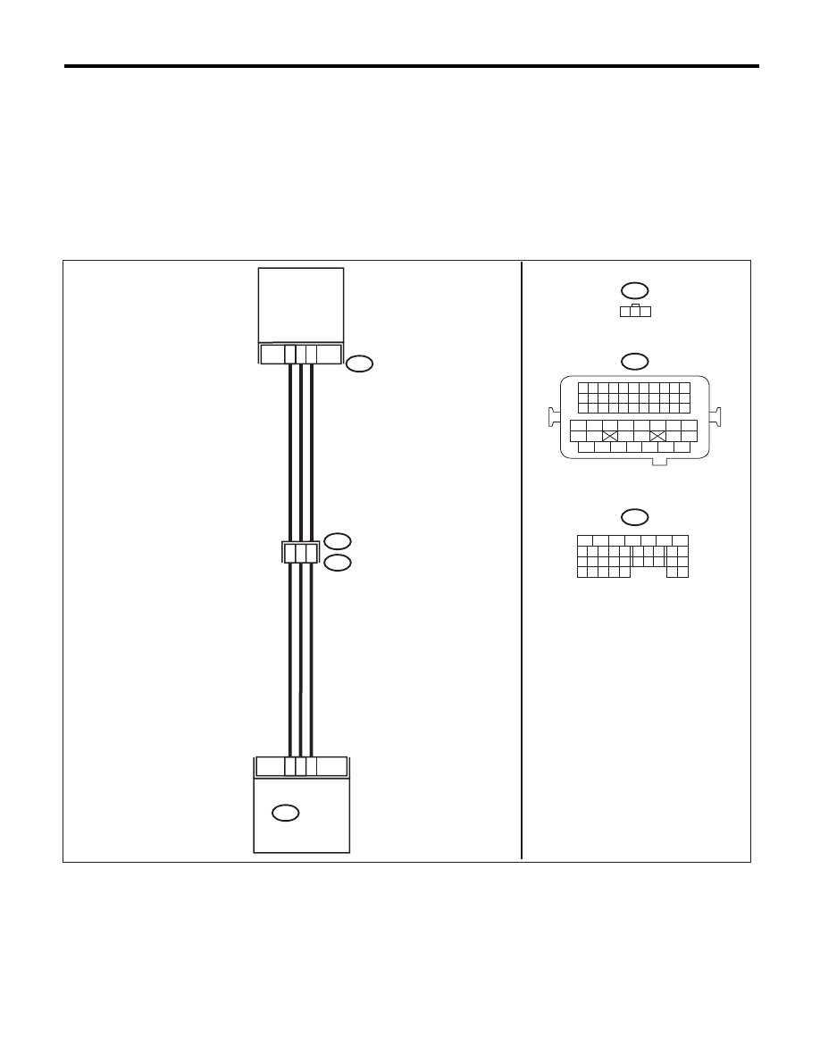
H: DTC P0068 MAP/MAF - THROTTLE POSITION CORRELATION
DTC DETECTING CONDITION:
• Two consecutive driving cycles with fault
• GENERAL DESCRIPTION <Ref. to GD(H4SO)-21, DTC P0068 MAP/MAF - THROTTLE POSITION
CORRELATION, Diagnostic Trouble Code (DTC) Detecting Criteria.>
CAUTION:
After repair or replacement of faulty parts, perform Clear Memory Mode <Ref. to EN(H4SO)(diag)-50,
OPERATION, Clear Memory Mode.>, and Inspection Mode <Ref. to EN(H4SO)(diag)-41, PROCEDURE,
Inspection Mode.>.
WIRING DIAGRAM:
EN-04029
5
6
7
8
2
1
9
4
3
10
24
22 23
25
11 12 13 14 15
26 27
28
16 17
18 19 20 21
33 34
29
32
30 31
19
20
7
B21
E2
2
3
1
E21
E21
ECM
B21
B134
1 2 3 4
12 13 14 15
5 6 7 8
16 17 18 19
9 10 11
20 21 22
23 24 25 26 27 28 29 30 31 32 33
35
34
37
36
39
38
41
40
43
42
44
45
47
46
49
48
51
50
53
52
54
B134
MANIFOLD
ABSOLUTE
PRESSURE
SENSOR
1 2 3
29
6
19

EN(H4SO)(diag)-102
Diagnostic Procedure with Diagnostic Trouble Code (DTC)
ENGINE (DIAGNOSTICS)
Step
Check
Yes
No
1
CHECK AIR INTAKE SYSTEM.
Are there holes, loose bolts or
disconnection of hose on air
intake system?
Repair the air
intake system.
Go to step 2.
2
CHECK MANIFOLD ABSOLUTE PRESSURE
SENSOR.
1) Start the engine and warm up engine until
coolant temperature is higher than 75°C
(167°F).
2) For AT models, set the select lever to “P”
range or “N” range, and for MT models, place
the shift lever in the neutral position.
3) Turn the A/C switch to OFF.
4) Turn all the accessory switches to OFF.
5) Read the data of intake manifold pressure
sensor signal using Subaru Select Monitor or
general scan tool.
NOTE:
• SUBARU SELECT MONITOR
For detailed operation procedure, refer to
“READ CURRENT DATA FOR ENGINE”. <Ref.
to EN(H4SO)(diag)-33, Subaru Select Moni-
tor.>
• General Scan Tool
For detailed operation procedures, refer to the
“General Scan Tool Instruction Manual”.
Is the measured value 73.3 —
106.6 kPa (550 — 800 mmHg,
21.65 — 31.50 inHg) when the
ignition is turned ON, and 20.0
— 46.7 kPa (150 — 350 mmHg,
5.91 — 13.78 inHg) during
idling?
Go to step 3.
Replace the mani-
fold absolute pres-
sure sensor. <Ref.
to FU(H4SO)-27,
Manifold Absolute
Pressure Sensor.>
3
CHECK THROTTLE OPENING ANGLE.
Read the data of throttle position signal using
Subaru Select Monitor or general scan tool.
NOTE:
• SUBARU SELECT MONITOR
For detailed operation procedure, refer to
“READ CURRENT DATA FOR ENGINE”. <Ref.
to EN(H4SO)(diag)-33, Subaru Select Moni-
tor.>
• General Scan Tool
For detailed operation procedures, refer to the
“General Scan Tool Instruction Manual”.
Is the measured value less than
5% when throttle is fully
closed?
Go to step 4.
Replace the elec-
tronic throttle con-
trol. <Ref. to
FU(H4SO)-12,
Throttle Body.>
4
CHECK THROTTLE OPENING ANGLE.
Is the measured value 85% or
more when throttle is fully
open?
Replace the mani-
fold absolute pres-
sure sensor. <Ref.
to FU(H4SO)-27,
Manifold Absolute
Pressure Sensor.>
Replace the elec-
tronic throttle con-
trol. <Ref. to
FU(H4SO)-12,
Throttle Body.>
Нет комментариевНе стесняйтесь поделиться с нами вашим ценным мнением.
Текст