Subaru Legacy III (2000-2003 year). Service manual — part 793
VDC-208
VDC (DIAGNOSTICS)
DIAGNOSTICS CHART WITH SELECT MONITOR
AL:DTC 51 VALVE RELAY ON FAILURE
DIAGNOSIS:
• Faulty valve relay
NOTE:
When DTC 74 inspection is carried out, DTC 51 is memorized.
TROUBLE SYMPTOM:
• ABS does not operate.
• VDC does not operate.
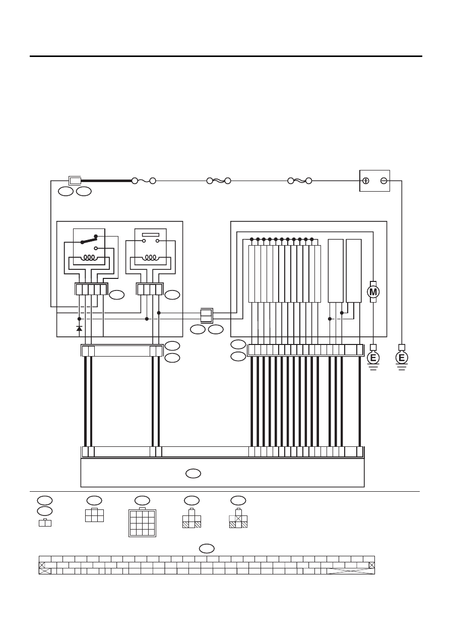
WIRING DIAGRAM:
VDC00150
10
9
11
12
15
13
16
14
VDC HYDRAULIC UNIT
VALVE RELAY
87
87a
VDC2
VDC1
4
6
86
1
85
30
30
86
85
87
5
VDC4
F90
VDC5
F91
F87
56 57
59 60
62 63
65
82 83
80
27
28
25
26
23
24
21
22
19
20
17
18
15
16
13
14
11
12
9
10
7
8
5
6
3
4
1
2
54
55
52
53
50
51
81
48
49
46
47
44
45
78
79
76
77
75
42
43
40
41
74
72
73
70
71
39
37
38
35
36
69
67
68
66
33
34
61
64
31
32
29
30
58
SBF-3 50A
VDC7
VDC6
MOTOR RELAY
VALVE RELAY
VDC CONTROL MODULE
22
10
27
47
F87
1
2
F89
VDC3
1
SBF-1 100A
RELAY BOX
F89
VDC1
1 2
F90
1
3
4 5 6
2
NO. 8 30A
FR OUTLET
FR INLET
RL OUTLET
RL INLET
RR OUTLET
RR INLET
PRIMAR
Y CUT
PRIMAR
Y SECTION
SECOND
AR
Y CUT
PRIMAR
Y
PRESSURE SENSOR
SECOND
A
R
Y
PRESSURE SENSOR
SECOND
AR
Y SECTION
FL OUTLET
FL INLET
51
30
3
31
4
23
50
24
25
2
26
36
76
77
78
29
4
5
1
6
2
7
3
8
85
86
87
87a
30
85
86
87
30
F91
VDC6
VDC7
1
2
3
4
5
6
7
8
9
10
11
12
13
14
15
16
BATTERY

VDC-209
VDC (DIAGNOSTICS)
DIAGNOSTICS CHART WITH SELECT MONITOR
Step
Value
Yes
No
1
CHECK CONTACT POINT OF VALVE RE-
LAY.
1) Turn ignition switch to OFF.
2) Remove valve relay from relay box.
3) Connect battery to valve relay terminals
No. 85 and No. 86.
4) Measure resistance between valve relay
terminals.
Terminals
No. 30 — No. 87:
Is the measured value less than the speci-
fied value?
0.5
Ω
Replace valve
relay.
2
CHECK CONTACT POINT OF VALVE RE-
LAY.
Measure resistance between valve relay termi-
nals.
Terminals
No. 30 — No. 87a:
Does the measured value exceed the specified
value?
1 M
Ω
Replace valve
relay.
3
CHECK CONTACT POINT OF VALVE RE-
LAY.
1) Disconnect battery from valve relay termi-
nals.
2) Measure resistance between valve relay
terminals.
Terminals
No. 30 — No. 87:
Does the measured value exceed the spec-
ified value?
1 M
Ω
Replace valve
relay.
4
CHECK CONTACT POINT OF VALVE RE-
LAY.
Measure resistance between valve relay termi-
nals.
Terminals
No. 30 — No. 87a:
Is the measured value less than the specified
value?
0.5
Ω
Replace valve
relay.
5
CHECK SHORT OF VALVE RELAY.
Measure resistance between valve relay termi-
nals.
Terminals
No. 86 — No. 87:
No. 86 — No. 87a:
Does the measured value exceed the specified
value?
1 M
Ω
Replace valve
relay.
6
CHECK BATTERY SHORT IN CONTACT
POINT CIRCUIT OF RELAY BOX.
1) Disconnect connector (F90) from relay box.
2) Measure voltage between relay box con-
nector and chassis ground.
Connector & terminal
(VDC4) No. 5 (+) — Chassis ground (
−−−−
):
(VDC4) No. 1 (+) — Chassis ground (
−−−−
):
Is the measured value less than the speci-
fied value?
1 V
Replace relay box.
Check fuse No. 8
and SBF3.

VDC-210
VDC (DIAGNOSTICS)
DIAGNOSTICS CHART WITH SELECT MONITOR
7
CHECK BATTERY SHORT IN CONTACT
POINT CIRCUIT OF RELAY BOX.
1) Turn ignition switch to ON.
2) Measure voltage between VDCH/U con-
nector and chassis ground.
Connector & terminal
(VDC4) No. 5 (+) — Chassis ground (
−−−−
):
(VDC4) No. 1 (+) — Chassis ground (
−−−−
):
Is the measured value less than the speci-
fied value?
1 V
Replace relay box.
Check fuse No. 8
and SBF3.
8
CHECK BATTERY SHORT IN CONTROL
SYSTEM HARNESS OF VALVE RELAY.
1) Turn ignition switch to OFF.
2) Disconnect connector from VDCCM.
3) Disconnect connector from VDCH/U.
4) Measure voltage between VDCCM connec-
tor and chassis ground.
Connector & terminal
(F87) No. 27 (+) — Chassis ground (
−−−−
):
(F87) No. 47 (+) — Chassis ground (
−−−−
):
Is the measured value less than the speci-
fied value?
1 V
Repair harness
between VDCCM
and relay box and
check all fuses.
9
CHECK BATTERY SHORT IN CONTROL
SYSTEM HARNESS OF VALVE RELAY.
1) Turn ignition switch to ON.
2) Measure voltage between VDCCM connec-
tor and chassis ground.
Connector & terminal
(F87) No. 27 (+) — Chassis ground (
−−−−
):
(F87) No. 47 (+) — Chassis ground (
−−−−
):
Is the measured value less than the speci-
fied value?
1 V
Repair harness
between VDCCM
and relay box and
check all fuses.
10
CHECK BATTERY SHORT IN CONTACT
POINT CIRCUIT OF RELAY BOX.
1) Disconnect connector VDC1 from relay
box.
2) Measure voltage between VDCH/U con-
nector and chassis ground.
Connector & terminal
(VDC1) No. 2 (+) — Chassis ground (
−−−−
):
Is the measured value less than the speci-
fied value?
1 V
Replace relay box.
11
CHECK BATTERY SHORT IN CONTACT
POINT CIRCUIT OF RELAY BOX.
1) Turn ignition switch to ON.
2) Measure voltage between VDCH/U con-
nector and chassis ground.
Connector & terminal
(VDC1) No. 2 (+) — Chassis ground (
−−−−
):
Is the measured value less than the speci-
fied value?
1 V
Replace relay box.
Step
Value
Yes
No

VDC-211
VDC (DIAGNOSTICS)
DIAGNOSTICS CHART WITH SELECT MONITOR
12
CHECK BATTERY SHORT OF SOLENOID
VALVE.
1) Turn ignition switch to OFF.
2) Measure voltage between VDCH/U con-
nector and chassis ground.
Connector & terminal
(VDC2) No. 2 (+) — Chassis ground (
−−−−
):
Is the measured value less than the speci-
fied value?
1 V
Replace VDCH/U
and check all
fuses. <Ref. to
VDC-8, VDC Con-
trol Module
(VDCCM).>
13
CHECK BATTERY SHORT OF SOLENOID
VALVE.
1) Turn ignition switch to ON.
2) Measure voltage between VDCH/U con-
nector and chassis ground.
Connector & terminal
(VDC2) No. 2 (+) — Chassis ground (
−−−−
):
Is the measured value less than the speci-
fied value?
1 V
Replace VDCH/U
and check all
fuses. <Ref. to
VDC-8, VDC Con-
trol Module
(VDCCM).>
14
CHECK BATTERY SHORT OF HARNESS.
1) Turn ignition switch to OFF.
2) Measure voltage between VDCCM connec-
tor and chassis ground.
Connector & terminal
(F87) No. 30 (+) — Chassis ground (
−−−−
):
(F87) No. 24 (+) — Chassis ground (
−−−−
):
(F87) No. 23 (+) — Chassis ground (
−−−−
):
(F87) No. 31 (+) — Chassis ground (
−−−−
):
(F87) No. 26 (+) — Chassis ground (
−−−−
):
(F87) No. 25 (+) — Chassis ground (
−−−−
):
(F87) No. 3 (+) — Chassis ground (
−−−−
):
(F87) No. 51 (+) — Chassis ground (
−−−−
):
(F87) No. 50 (+) — Chassis ground (
−−−−
):
(F87) No. 4 (+) — Chassis ground (
−−−−
):
(F87) No. 2 (+) — Chassis ground (
−−−−
):
(F87) No. 29 (+) — Chassis ground (
−−−−
):
Is the measured value less than the speci-
fied value?
1 V
Repair harness
between VDCH/U
and VDCCM and
check all fuses.
15
CHECK BATTERY SHORT OF HARNESS.
1) Turn ignition switch to ON.
2) Measure voltage between VDCCM connec-
tor and chassis ground.
Connector & terminal
(F87) No. 30 (+) — Chassis ground (
−−−−
):
(F87) No. 24 (+) — Chassis ground (
−−−−
):
(F87) No. 23 (+) — Chassis ground (
−−−−
):
(F87) No. 31 (+) — Chassis ground (
−−−−
):
(F87) No. 26 (+) — Chassis ground (
−−−−
):
(F87) No. 25 (+) — Chassis ground (
−−−−
):
(F87) No. 3 (+) — Chassis ground (
−−−−
):
(F87) No. 51 (+) — Chassis ground (
−−−−
):
(F87) No. 50 (+) — Chassis ground (
−−−−
):
(F87) No. 4 (+) — Chassis ground (
−−−−
):
(F87) No. 2 (+) — Chassis ground (
−−−−
):
(F87) No. 29 (+) — Chassis ground (
−−−−
):
Is the measured value less than the speci-
fied value?
1 V
Repair harness
between VDCH/U
and VDCCM and
check all fuses.
Step
Value
Yes
No
Нет комментариевНе стесняйтесь поделиться с нами вашим ценным мнением.
Текст