Subaru Legacy III (2000-2003 year). Service manual — part 648
FS-4
FRONT SUSPENSION
GENERAL DESCRIPTION
C: CAUTION
• Wear working clothing, including a cap, protec-
tive goggles, and protective shoes during opera-
tion.
• Remove contamination including dirt and corro-
sion before removal, installation or disassembly.
• Keep the disassembled parts in order and pro-
tect them from dust or dirt.
• Before removal, installation or disassembly, be
sure to clarify the failure. Avoid unnecessary re-
moval, installation, disassembly, and replacement.
• Use SUBARU genuine grease etc. or the equiv-
alent. Do not mix grease etc. with that of another
grade or from other manufacturers.
• Be sure to tighten fasteners including bolts and
nuts to the specified torque.
• Place shop jacks or safety stands at the specified
points.
• Apply grease onto sliding or revolution surfaces
before installation.
• Before installing O-rings or snap rings, apply suf-
ficient amount of grease to avoid damage and de-
formation.
• Before securing a part on a vise, place cushion-
ing material such as wood blocks, aluminum plate,
or shop cloth between the part and the vise.
FS-5
FRONT SUSPENSION
GENERAL DESCRIPTION
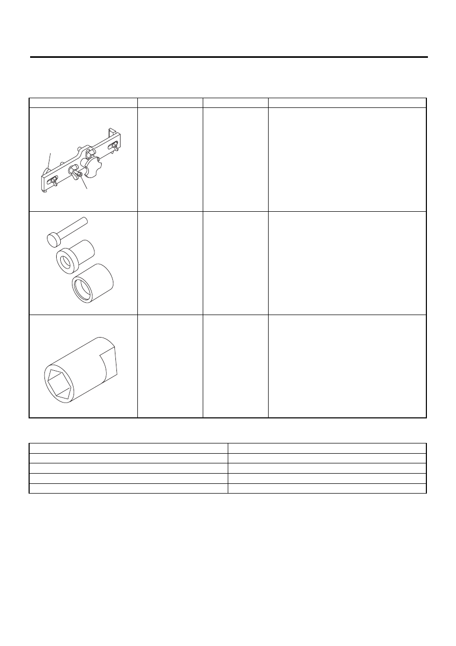
D: PREPARATION TOOL
1. SPECIAL TOOLS
2. GENERAL PURPOSE TOOLS
ILLUSTRATION
TOOL NUMBER
DESCRIPTION
REMARKS
927380002
ADAPTER
Used as an adapter for camber & caster gauge
when measuring camber and caster.
(1) 28199AC000 PLATE
(2) 28199AC010 BOLT
927680000
INSTALLER &
REMOVER SET
Used for replacing transverse link bushing.
927760000
STRUT MOUNT
SOCKET
Used for disassembling and assembling strut and
shock mount.
TOOL NAME
REMARKS
Alignment gauge
Used for wheel alignment measurement.
Turning radius gauge
Used for wheel alignment measurement.
Toe-in gauge
Used for toe-in measurement.
Dial gauge
Used for damper strut measurement.
ST-927380002
( 1 )
( 2 )
ST-927680000
ST-927760000
FS-6
FRONT SUSPENSION
WHEEL ALIGNMENT
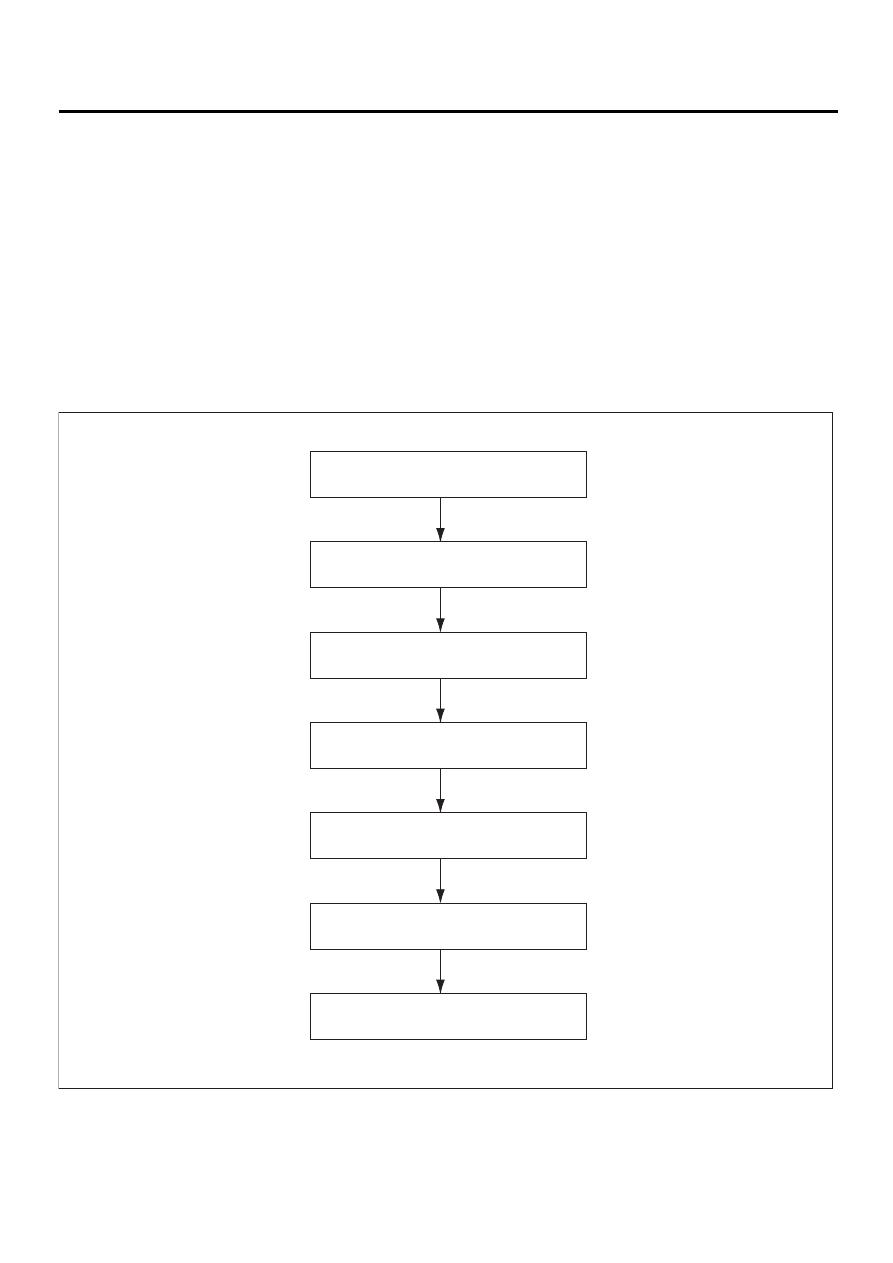
2. Wheel Alignment
A: INSPECTION
Check the following items before taking wheel alignment measurement.
Check items before taking wheel alignment measurement:
• tire air pressure
• unbalanced right and left tire wear, size difference
• tire run-out
• ball joint excessive play, wear
• tie rod end excessive play, wear
• wheel bearing excessive play
• right and left wheel base imbalance
• steering link part deformed, excessive play
• suspension part deformed, excessive play
Check, adjust and/or measure wheel alignment in accordance with procedures indicated in figure:
WHEEL ARCH HEIGHT (FRONT AND REAR)
CAMBER (FRONT AND REAR)
CASTER (FRONT)
WHEEL STEERING ANGLE
FRONT TOE-IN
REAR TOE-IN
THRUST ANGLE (REAR)
FS-00059
FS-7
FRONT SUSPENSION
WHEEL ALIGNMENT
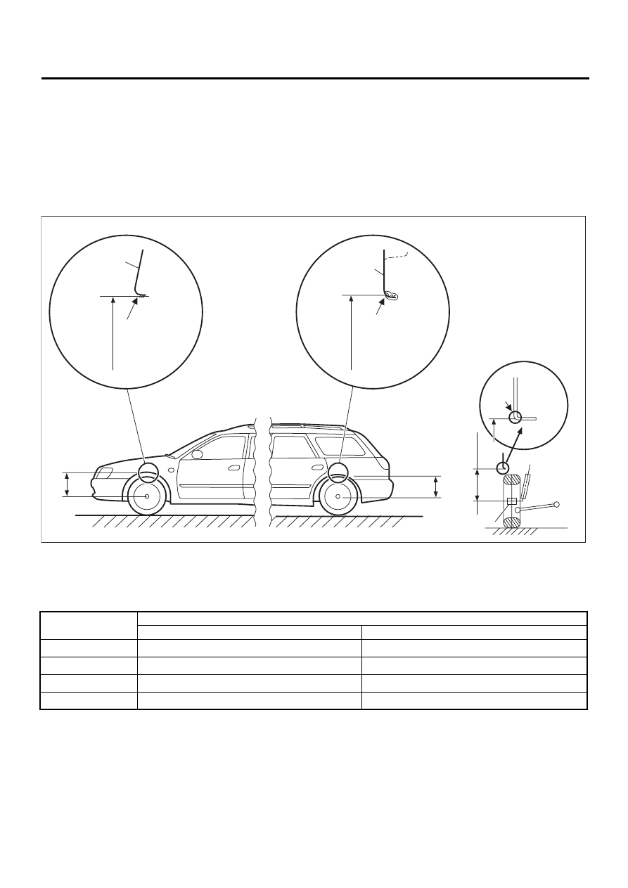
1. WHEEL ARCH HEIGHT
1) Set vehicle on a level surface.
2) Set vehicle to “curb weight” conditions. (Empty luggage compartment, install spare tire, jack, service tools,
and top up fuel tank.)
3) Set steering wheel in a straight line, then move the vehicle straight ahead more than 5 m (16 ft) to settle
the suspension.
4) Suspend thread from wheel arch (point “A” in figure below) to determine a point directly above center of
wheel.
5) Measure distance between measuring point “A” and center of wheel.
* Model for Australia: 431
+12
/
−
24
mm (16.97
+0.47
/
−
0.94
in)
(1) Front fender
(4) Front wheel arch height
(7) Measuring point
(2) Outer rar quarter
(5) Rear wheel arch height
(8) End of spindle
(3) Wheel arch height
(6) Cross-section of arch
Model
Specified wheel arch height
Front
Rear
Sedan
388
+12
/
−
24
mm (15.28
+0.47
/
−
0.94
in)
371
+12
/
−
24
mm (14.61
+0.47
/
−
0.94
in)
Wagon
388
+12
/
−
24
mm (15.28
+0.47
/
−
0.94
in)
381
+12
/
−
24
mm (15.00
+0.47
/
−
0.94
in)
OUTBACK
428
+12
/
−
24
mm (16.85
+0.47
/
−
0.94
in)
421
+12
/
−
24
mm (16.57
+0.47
/
−
0.94
in)*
TURBO
378
+12
/
−
24
mm (14.88
+0.47
/
−
0.94
in)
361
+12
/
−
24
mm (14.21
+0.47
/
−
0.94
in)
FS-00060
A
A
A
( 1 )
( 2 )
( 3 )
( 3 )
( 3 )
( 4 )
( 5 )
( 6 )
( 8 )
( 7 )
Нет комментариевНе стесняйтесь поделиться с нами вашим ценным мнением.
Текст