Subaru Legacy III (2000-2003 year). Service manual — part 382
EN(H6DO)-330
ENGINE (DIAGNOSTICS)
DIAGNOSTIC PROCEDURE WITH DIAGNOSTIC TROUBLE CODE (DTC)
CS:DTC P1712 — ENGINE TORQUE CONTROL SIGNAL #2 CIRCUIT MALFUNC-
TION —
• DTC DETECTING CONDITION:
• Two consecutive driving cycles with fault
• TROUBLE SYMPTOM:
• Excessive shift shock
CAUTION:
After repair or replacement of faulty parts, conduct Clear Memory Mode <Ref. to EN(H6DO)-54, OP-
ERATION, Clear Memory Mode.> and Inspection Mode <Ref. to EN(H6DO)-47, OPERATION, Inspec-
tion Mode.>.
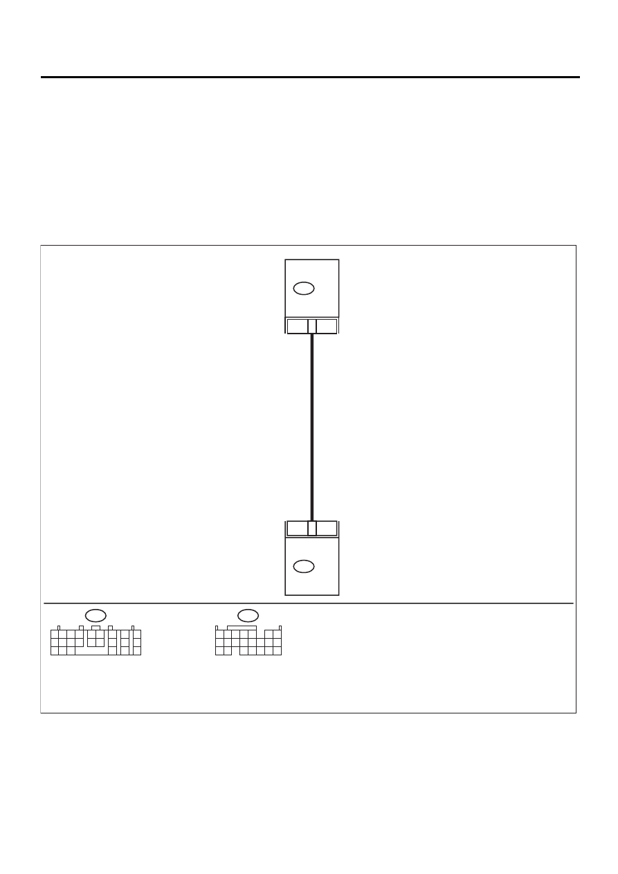
• WIRING DIAGRAM:
EN-01102
B56
B134
18
14
TCM
B56
B134 ECM
1 2
7
8
9
5 6
3 4
10 11 12
19 20 21
13
14 15
16
17
18
22
23
24
1 2 3 4
10 11 12
19 20 21
13
5
6
14 15
7
8 9
16 17
18
22

EN(H6DO)-331
ENGINE (DIAGNOSTICS)
DIAGNOSTIC PROCEDURE WITH DIAGNOSTIC TROUBLE CODE (DTC)
Step
Value
Yes
No
1
CHECK INPUT SIGNAL FOR ECM.
1) Turn ignition switch to ON.
2) Measure voltage between ECM and chas-
sis ground.
Connector & terminal
(B134) No. 18 (+) — Chassis ground (
−−−−
):
Does the measured value exceed the spec-
ified value?
4.5 V
2
CHECK INPUT SIGNAL FOR ECM.
Measure voltage between ECM and chassis
ground.
Connector & terminal
(B134) No. 18 (+) — Chassis ground (
−−−−
):
Does the measured value exceed the specified
value?
10 V
Repair battery
short circuit in har-
ness between
ECM and TCM
connector.
3
CHECK POOR CONTACT.
Check poor contact in ECM connector.
Is there poor contact in ECM connector?
There is poor contact.
Repair poor con-
tact in ECM con-
nector.
Contact SUBARU
distributor service.
NOTE:
Inspection by DTM
is required, be-
cause probable
cause is deteriora-
tion of multiple
parts.
4
CHECK HARNESS BETWEEN ECM AND
TCM CONNECTOR.
1) Turn ignition switch to OFF.
2) Disconnect connectors from ECM and
TCM.
3) Measure resistance of harness between
ECM and TCM connector.
Connector & terminal
(B134) No. 18 — (B56) No. 14:
Is the measured value less than the speci-
fied value?
1
Ω
Repair open circuit
in harness
between ECM and
TCM connector.
5
CHECK HARNESS BETWEEN ECM AND
TCM CONNECTOR.
Measure resistance of harness between ECM
and chassis ground.
Connector & terminal
(B134) No. 18 — Chassis ground:
Is the measured value less than the specified
value?
10
Ω
Repair ground
short circuit in har-
ness between
ECM and TCM
connector.
6
CHECK POOR CONTACT.
Check poor contact in TCM connector.
Is there poor contact in TCM connector?
There is poor contact.
Repair poor con-
tact in TCM con-
nector.
Replace TCM.
<Ref. to AT-76,
Transmission Con-
trol Module
(TCM).>

EN(H6DO)-332
ENGINE (DIAGNOSTICS)
GENERAL DIAGNOSTIC TABLE
20.General Diagnostic Table
A: INSPECTION
1. ENGINE
NOTE:
Malfunction of parts other than those listed is also possible. <Ref. to ME(H6DO)-74, Engine Trouble in Gen-
eral.>
Symptom
Problem parts
1. Engine stalls during idling.
1) Idle air control solenoid valve
2) Intake manifold pressure sensor
3) Intake air temperature sensor
4) Ignition parts (*1)
5) Engine coolant temperature sensor (*2)
6) Crankshaft position sensor (*3)
7) Camshaft position sensor (*3)
8) Fuel injection parts (*4)
9) EGR valve
2. Rough idling
1) Idle air control solenoid valve
2) Intake manifold pressure sensor
3) Intake air temperature sensor
4) Engine coolant temperature sensor (*2)
5) Ignition parts (*1)
6) Air intake system (*5)
7) Fuel injection parts (*4)
8) Throttle position sensor
9) Crankshaft position sensor (*3)
10) Camshaft position sensor (*3)
11) Oxygen sensor
12) Fuel pump and fuel pump relay
13) EGR valve
3. Engine does not return to idle.
1) Idle air control solenoid valve
2) Engine coolant temperature sensor
3) Accelerator cable (*6)
4) Throttle position sensor
5) Intake manifold pressure sensor
6) Intake air temperature sensor
7) EGR valve
4. Poor acceleration
1) Intake manifold pressure sensor
2) Intake air temperature sensor
3) Throttle position sensor
4) Fuel injection parts (*4)
5) Fuel pump and fuel pump relay
6) Engine coolant temperature sensor (*2)
7) Crankshaft position sensor (*3)
8) Camshaft position sensor (*3)
9) A/C switch and A/C cut relay
10) Engine torque control signal circuit
11) Ignition parts (*1)
12) EGR valve
5. Engine stalls or engine sags or hesitates at
acceleration.
1) Intake manifold pressure sensor
2) Intake air temperature sensor
3) Engine coolant temperature sensor (*2)
4) Crankshaft position sensor (*3)
5) Camshaft position sensor (*3)
6) Purge control solenoid valve
7) Fuel injection parts (*4)
8) Throttle position sensor
9) Fuel pump and fuel pump relay
10) EGR valve

EN(H6DO)-333
ENGINE (DIAGNOSTICS)
GENERAL DIAGNOSTIC TABLE
*1: Check ignition coil & ignitor assembly and spark plug.
*2: Indicate the symptom occurring only in cold temperatures.
*3: Ensure the secure installation.
*4: Check fuel injector, fuel pressure regulator and fuel filter.
*5: Inspect air leak in air intake system.
*6: Adjust accelerator cable.
2. AUTOMATIC TRANSMISSION
NOTE:
Check general diagnostics table with non-conformity symptom for automatic transmission. <Ref. to AT-2, Ba-
sic Diagnostic Procedure.>
6. Surge
1) Intake manifold pressure sensor
2) Intake air temperature sensor
3) Engine coolant temperature sensor (*2)
4) Crankshaft position sensor (*3)
5) Camshaft position sensor (*3)
6) Fuel injection parts (*4)
7) Throttle position sensor
8) Fuel pump and fuel pump relay
9) EGR valve
7. Spark knock
1) Intake manifold pressure sensor
2) Intake air temperature sensor
3) Engine coolant temperature sensor
4) Knock sensor
5) Fuel injection parts (*4)
6) Fuel pump and fuel pump relay
8. After burning in exhaust system
1) Intake manifold pressure sensor
2) Intake air temperature sensor
3) Engine coolant temperature sensor (*2)
4) Fuel injection parts (*4)
5) Fuel pump and fuel pump relay
Symptom
Problem parts
Нет комментариевНе стесняйтесь поделиться с нами вашим ценным мнением.
Текст