Subaru Legacy III (2000-2003 year). Service manual — part 849
PS-84
POWER ASSISTED SYSTEM (POWER STEERING)
OIL PUMP
5) Temporarily install rear cover to front casing.
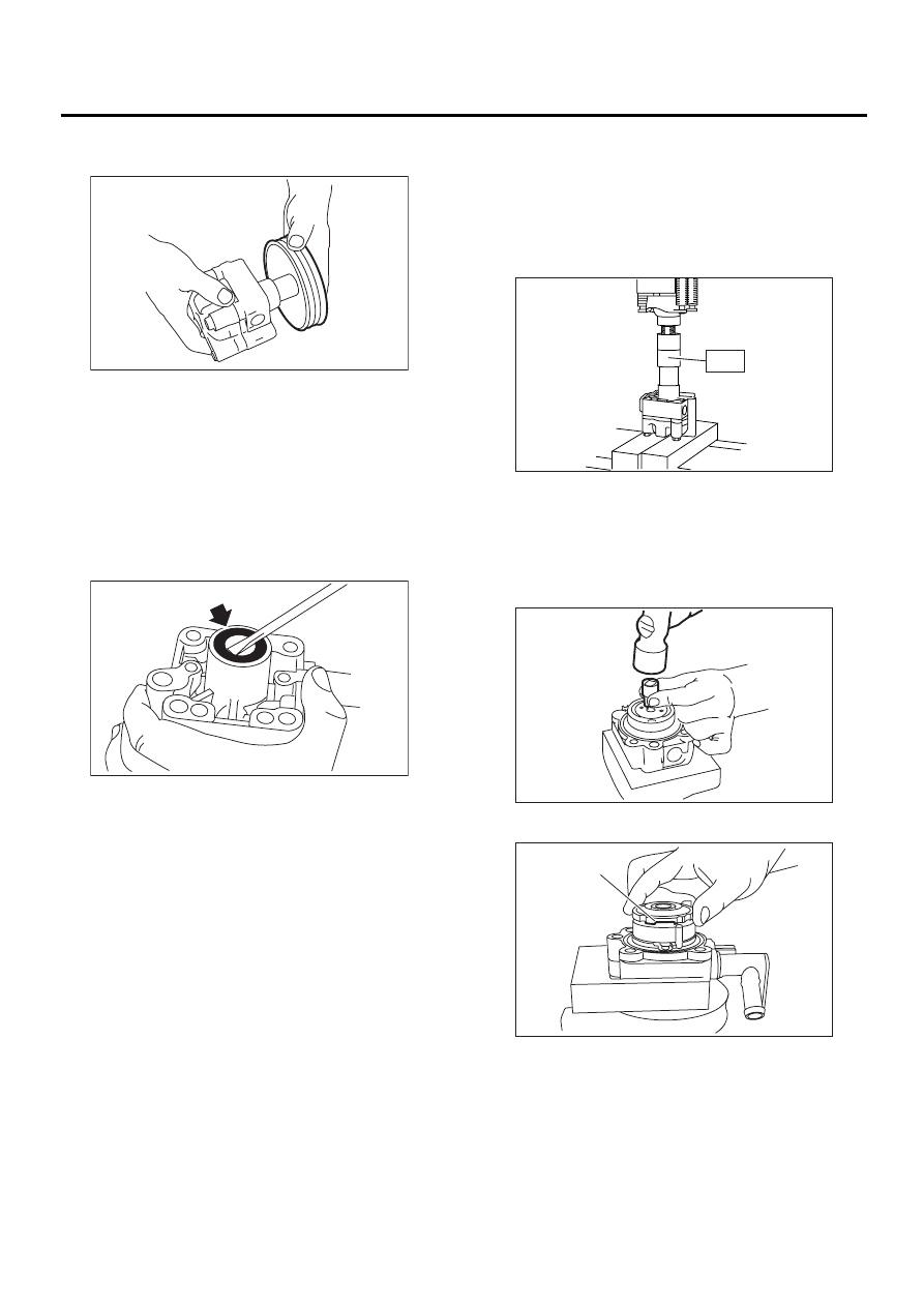
6) Remove oil pump pulley.
7) Place oil pump in a vise.
CAUTION:
Do not place oil pump directly in the vise, use
soft pads and hold oil pump lightly to protect
the pump.
8) Pry oil seal off using a screwdriver.
CAUTION:
Be careful not to scratch inner surface of cas-
ing.
D: ASSEMBLY
1) Reassembly precautions
(1) Whenever O-rings, oil seals, and snap rings
are removed, they must be replaced with new
ones.
(2) Thoroughly wash parts and allow to dry.
They must be kept free from cleaning oil and
dust.
(3) Reassembly procedure must be performed
in clean place. Ensure that parts are kept away
from waste threads or other dust particles.
(4) Cleaning oil tends to stay inside the front
casing. Remove it completely by blowing com-
pressed air.
(5) Ensure that parts are free from rust. (Use
specified hydraulic oil for rust prevention after
cleaning and drying.)
(6) Reverse the sequence of disassembly pro-
cedures.
2) Apply grease to oil seal and inner surface of front
casing (at bearing location).
CAUTION:
Make sure that the front body internal surfaces
are free from damage.
3) Temporarily install rear cover to front body.
4) Attach ST to front body. Using a press, install oil
seal.
ST
34199AE030
INSTALLER
5) Install pump pulley to front body.
6) Using ST, place oil pump in a vise.
ST
34199AE020
ATTACHMENT
7) Remove rear cover.
8) Using 10-mm box wrench, tap retaining ring into
shaft groove.
9) Install pressure plate as shown in the figure.
10) Apply specified hydraulic oil to O-rings and fit
them into front casing and pressure plate.
11) Install seal ring to pressure plate.
PS-00236
PS-00237
(1) Groove
PS-00238
ST
PS-00239
PS-00240
( 1 )
PS-85
POWER ASSISTED SYSTEM (POWER STEERING)
OIL PUMP
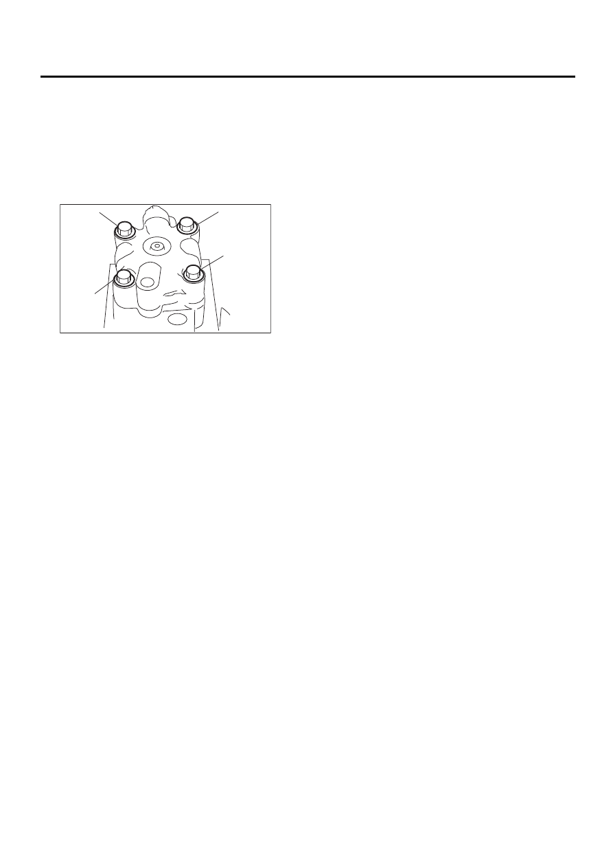
12) With knock pin positions aligned, install rear
cover.
Tightening torque:
27.5 N·m (2.8 kgf-m, 20.3 ft-lb)
CAUTION:
Loosely tighten bolts in the sequence (A), (B),
(C), and (D) shown in figure. Then, tighten in the
same sequence.
13) When reassembly procedures have been com-
pleted, turn shaft by hand to ensure it turns smooth-
ly. If it binds or other unusual conditions are
evident, disassemble again and check for foreign
matter trapped on sliding surfaces and improper in-
stallation. Eliminate the cause of trouble.
14) Check followings by referring to “CHECK” arti-
cle.
• Excessive play in pulley shaft
• Ditch deflection of pulley
• Resistance to rotation of pulley
• Measurement of generated oil pressure
PS-00241
( A )
( B )
( C )
( D )
PS-86
POWER ASSISTED SYSTEM (POWER STEERING)
OIL PUMP
E: INSPECTION
1. BASIC INSPECTION
Perform the following inspection procedures and repair or replace defective parts.
• In accordance with the following table, check all removed parts for wear and damage, and make repair or
replacement if necessary.
Part name
Description
Remedy
1. Front casing
1) Damage on body surfaces
2) Excessive wear on hole, into which spool
valve is inserted.
3) Wear and damage on cartridge assembly
mounting surface
4) Wear and damage on surfaces in contact with
shaft and oil seal
Replace with a new one together with spool
valve as selective fit is made.
2. Rear cover
1) Damage on body surfaces
2) Wear and damage on sliding surfaces
Replace with a new one.
3. Shaft
1) Shaft bend
2) Wear and damage on surfaces in contact with
bushing and oil seal
3) Wear and damage on rotor mounting surfaces
4) Bearing damage
Replace with a new one.
4. Pressure plate
Wear and damage on sliding surfaces
Replace with a new one.
5. Cam ring
Ridge wear on sliding surfaces
If damage is serious, replace with a new car-
tridge assembly.
6. Vane
Excessive wear on nose radius and side sur-
faces
7. Rotor
1) Wear and damage on sliding surfaces
2) Ridge wear on vane sliding grooves (If light
leaks with vane in slit against light source)
3) Damage resulting from snap ring removal
Correct with oil stone. If damage is serious,
replace with a new cartridge assembly.
8. Connector
Damage on threads
Replace with a new one.
9. Spring
Damage
Replace with a new one.
10. Bolts and nuts
Damage on threads
Replace with a new one.
No.
Parts
Inspection
Corrective action
1
Oil pump (Exterior)
(1) Crack, damage or oil leakage
Replace oil pump with a new one.
(2) Play of pulley shaft
Measure radial play and axial play.
If any of these exceeds the service limit, replace oil
pump with a new one.
2
Pulley
(1) Damage
Replace it with a new one.
(2) Bend
Measure V ditch deflection.
If it exceeds the service limit, replace pulley with a
new one.
3
Oil pump (Interior)
(1) Defect or burning of vane pump
Check resistance to rotation of pulley.
If it is past the service limit, replace oil pump with a
new one.
(2) Bend in the shaft or damage to
bearing
Oil pump emits a noise that is markedly different in
tone and loudness from a sound of a new oil pump
when turning with a string put around its pulley,
replace oil pump with a new one.
4
O-ring
Crack or deterioration
Replace it with a new one.
5
Bracket
Crack
Replace it with a new one.
PS-87
POWER ASSISTED SYSTEM (POWER STEERING)
OIL PUMP
2. SERVICE LIMIT
Make a measurement as follows. If it exceeds the
specified service limit, replace the parts with new
ones.
CAUTION:
• Fix oil pump on a vise to make a measure-
ment. At this time, hold oil pump with the least
possible force between two wood pieces.
• Do not set outside of flow control valve or
pulley on a vise; otherwise outside or pulley
might be deformed. Select properly sized wood
pieces.
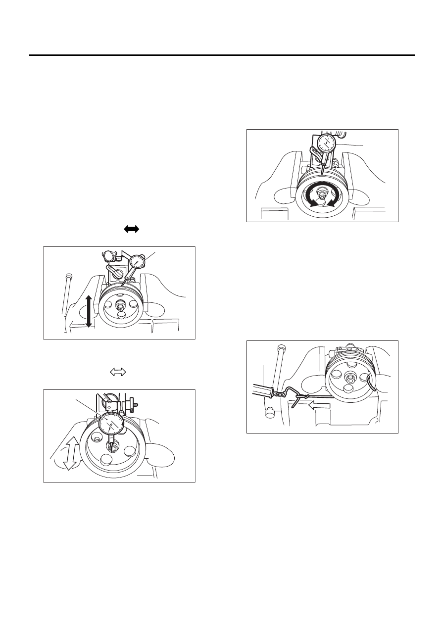
1) Play of pulley shaft
On condition:
P: 9.8 N (1.0 kgf, 2.2 lb)
Service limit:
Radial play (Direction
)
0.4 mm (0.016 in) or less
Axial play (Direction
)
0.6 mm (0.024 in) or less
2) Ditch deflection of pulley
Service limit:
1.0 mm (0.039 in) or less
NOTE:
Read the value for one surface of V ditch, and then
the value for another off the dial.
3) Resistance to rotation of pulley
Service limit:
Maximum load; 9.22 N (0.94 kgf, 2.07 lb) or
less
NOTE:
• A rather higher value may be indicated when pul-
ley starts turning.
• Measure the load during rotation and make a
judgment.
(1) Dial indicator
(1) Dial indicator
PS-00145
( 1 )
P
PS-00146
( 1 )
P
(1) Dial indicator
(1) Spring balance
PS-00147
( 1 )
PS-00148
( 1 )
Нет комментариевНе стесняйтесь поделиться с нами вашим ценным мнением.
Текст