Subaru Legacy III (2000-2003 year). Service manual — part 454
SC(H4DOSTC)-4
STARTING/CHARGING SYSTEMS
GENERAL DESCRIPTION
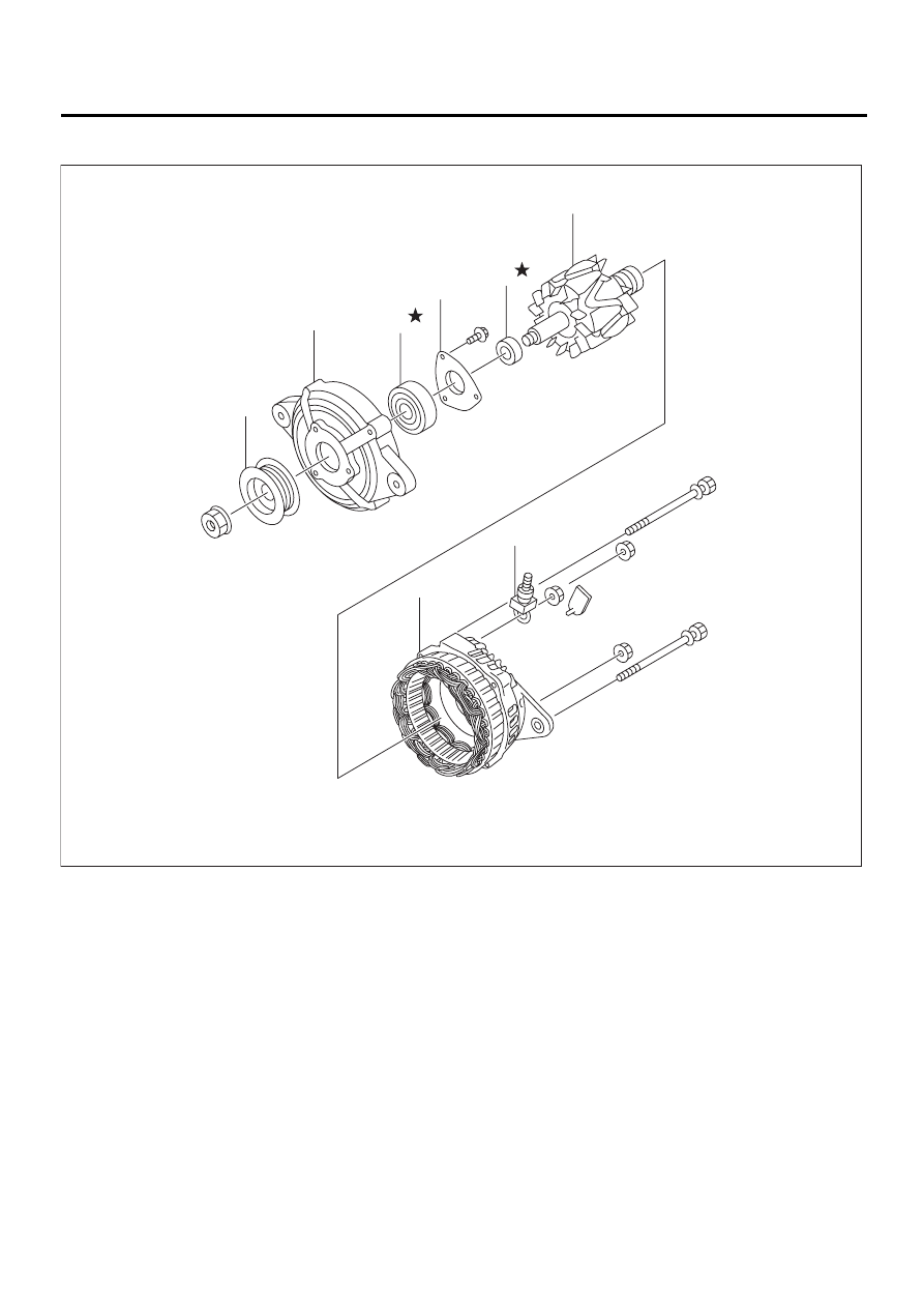
2. GENERATOR
(1) Pulley
(4) Bearing retainer
(7) Rear cover ASSY
(2) Front cover
(5) Ball bearing
(8) Terminal
(3) Ball bearing
(6) Rotor
SC-00147
( 1 )
( 2 )
( 3 )
( 4 )
( 5 )
( 6 )
( 7 )
( 8 )
SC(H4DOSTC)-5
STARTING/CHARGING SYSTEMS
GENERAL DESCRIPTION
C: CAUTION
• Wear working clothing, including a cap, protec-
tive goggles, and protective shoes during opera-
tion.
• Remove contamination including dirt and corro-
sion before removal, installation or disassembly.
• Keep the disassembled parts in order and pro-
tect them from dust or dirt.
• Before removal, installation or disassembly, be
sure to clarify the failure. Avoid unnecessary re-
moval, installation, disassembly, and replacement.
• Be careful not to burn your hands, because each
part in the vehicle is hot after running.
• Be sure to tighten fasteners including bolts and
nuts to the specified torque.
• Place shop jacks or safety stands at the specified
points.
• Before disconnecting electrical connectors of
sensors or units, be sure to disconnect the ground
cable from battery.
SC(H4DOSTC)-6
STARTING/CHARGING SYSTEMS
STARTER
2. Starter
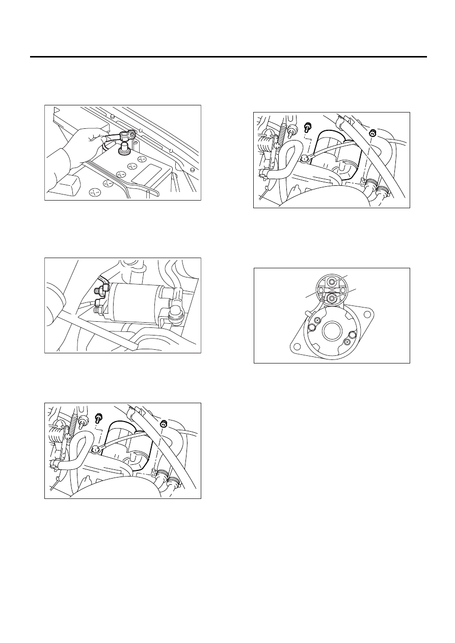
A: REMOVAL
1) Disconnect the ground cable from battery.
2) Remove the intercooler.
<Ref. to IN(H4DOSTC)-13, REMOVAL, Intercool-
er.>
3) Disconnect the connector and terminal from
starter.
4) Remove the starter from transmission.
B: INSTALLATION
Install in the reverse order of removal.
Tightening torque:
50 N·m (5.1 kgf-m, 37 ft-lb)
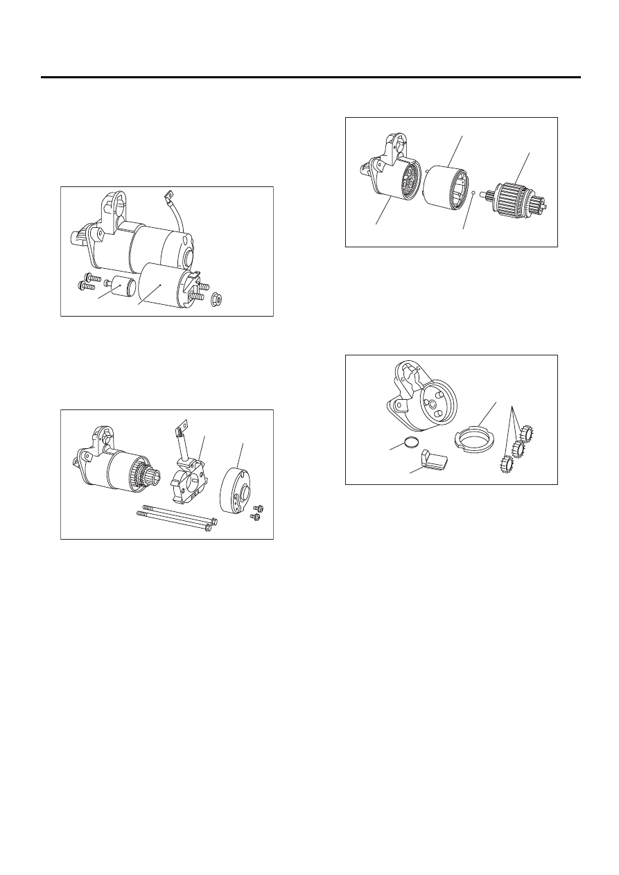
C: DISASSEMBLY
1. STARTER ASSEMBLY
1) Loosen the nut which holds terminal M of switch
assembly, and then disconnect the connector.
(A) Terminal
(B) Connector
FU-00009
SC-00006
( A )
( B )
SC-00007
(A) Terminal M
(B) Terminal B
(C) Terminal S
SC-00007
SC-00148
( A )
( B )
( C )
SC(H4DOSTC)-7
STARTING/CHARGING SYSTEMS
STARTER
2) Remove the bolts which hold switch assembly,
and then remove the switch assembly, plunger and
plunger spring from starter as a unit.
NOTE:
Be careful because the pinion gap adjustment
washer may sometimes be used on the mounting
surface of switch assembly.
3) Remove both through-bolts and brush holder
screws, and then detach the rear cover and brush
holder.
4) Remove the armature and yoke from front brack-
et.
5) Remove the packing A, planetary gear, packing
B and plate.
(A) Switch ASSY
(B) Plunger
(A) Brush holder
(B) Rear bracket
SC-00149
( A )
( B )
SC-00150
( A )
( B )
(A) Armature
(B) Ball
(C) Yoke
(D) Front bracket
(A) Packing A
(B) Planetary gear
(C) Plate
(D) Packing B
SC-00151
( A )
( B )
( C )
( D )
SC-00152
( D )
( C )
( B )
( A )
Нет комментариевНе стесняйтесь поделиться с нами вашим ценным мнением.
Текст