Subaru Legacy III (2000-2003 year). Service manual — part 99
EN(H4SO)-8
ENGINE (DIAGNOSTICS)
GENERAL DESCRIPTION
• The OBD-II diagnostics procedure is different
from the usual diagnostics procedure. When trou-
bleshooting OBD-II vehicles, connect Subaru Se-
lect Monitor or the OBD-II general scan tool to the
vehicle.
2. ENGINE AND EMISSION CONTROL SYS-
TEM
• The Multipoint Fuel Injection (MFI) system is a
system that supplies the optimum air-fuel mixture
to the engine for all the various operating condi-
tions through the use of the latest electronic tech-
nology.
With this system fuel, which is pressurized at a con-
stant pressure, is injected into the intake air pas-
sage of the cylinder head. The injection quantity of
fuel is controlled by an intermittent injection system
where the electro-magnetic injection valve (fuel in-
jector) opens only for a short period of time, de-
pending on the quantity of air required for one cycle
of operation. In actual operation, the injection quan-
tity is determined by the duration of an electric
pulse applied to the fuel injector and this permits
simple, yet highly precise metering of the fuel.
• Further, all the operating conditions of the engine
are converted into electric signals, and this results
in additional features of the system, such as large
improved adaptability, easier addition of compen-
sating element, etc.
The MFI system also has the following features:
• Reduced emission of harmful exhaust gases.
• Reduced in fuel consumption.
• Increased engine output.
• Superior acceleration and deceleration.
• Superior startability and warm-up perfor-
mance in cold weather since compensation is
made for coolant and intake air temperature.
3. AUTOMATIC TRANSMISSION AND
ELECTRONIC-HYDRAULIC CONTROL SYS-
TEM
The electronic-hydraulic control system consists of
various sensors and switches, a transmission con-
trol module (TCM) and the hydraulic controller in-
cluding solenoid valves. The system controls the
transmission proper including shift control, lock-up
control, overrunning clutch control, line pressure
control and shift timing control. It also controls the
AWD transfer clutch. In other words, the system
detects various operating conditions from various
input signals and sends output signals to shift sole-
noids 1, 2 and low clutch timing solenoid and 2-4
brake timing solenoid, line pressure duty solenoid,
lock-up duty solenoid, transfer duty solenoid and 2-
4 brake duty solenoid (a total of eight solenoids).
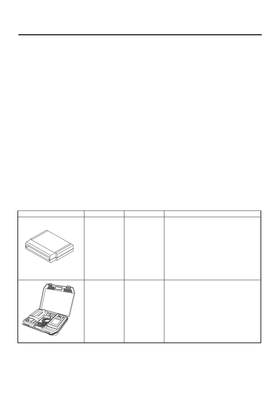
D: PREPARATION TOOL
ILLUSTRATION
TOOL NUMBER
DESCRIPTION
REMARKS
24082AA210
(Newly adopted
tool)
CARTRIDGE
Troubleshooting for electrical systems.
22771AA030
SELECT MONI-
TOR KIT
Troubleshooting for electrical systems.
• English: 22771AA030 (Without printer)
• German: 22771AA070 (Without printer)
• French: 22771AA080
(Without printer)
• Spanish: 22771AA090 (Without printer)
ST24082AA210
ST22771AA030
EN(H4SO)-9
ENGINE (DIAGNOSTICS)
GENERAL DESCRIPTION
MEMO:
EN(H4SO)-10
ENGINE (DIAGNOSTICS)
ELECTRICAL COMPONENTS LOCATION
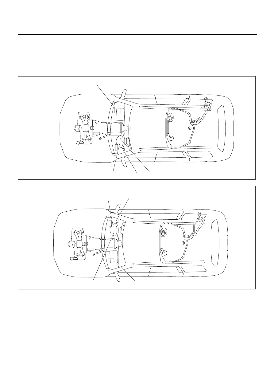
4. Electrical Components Location
A: LOCATION
1. ENGINE
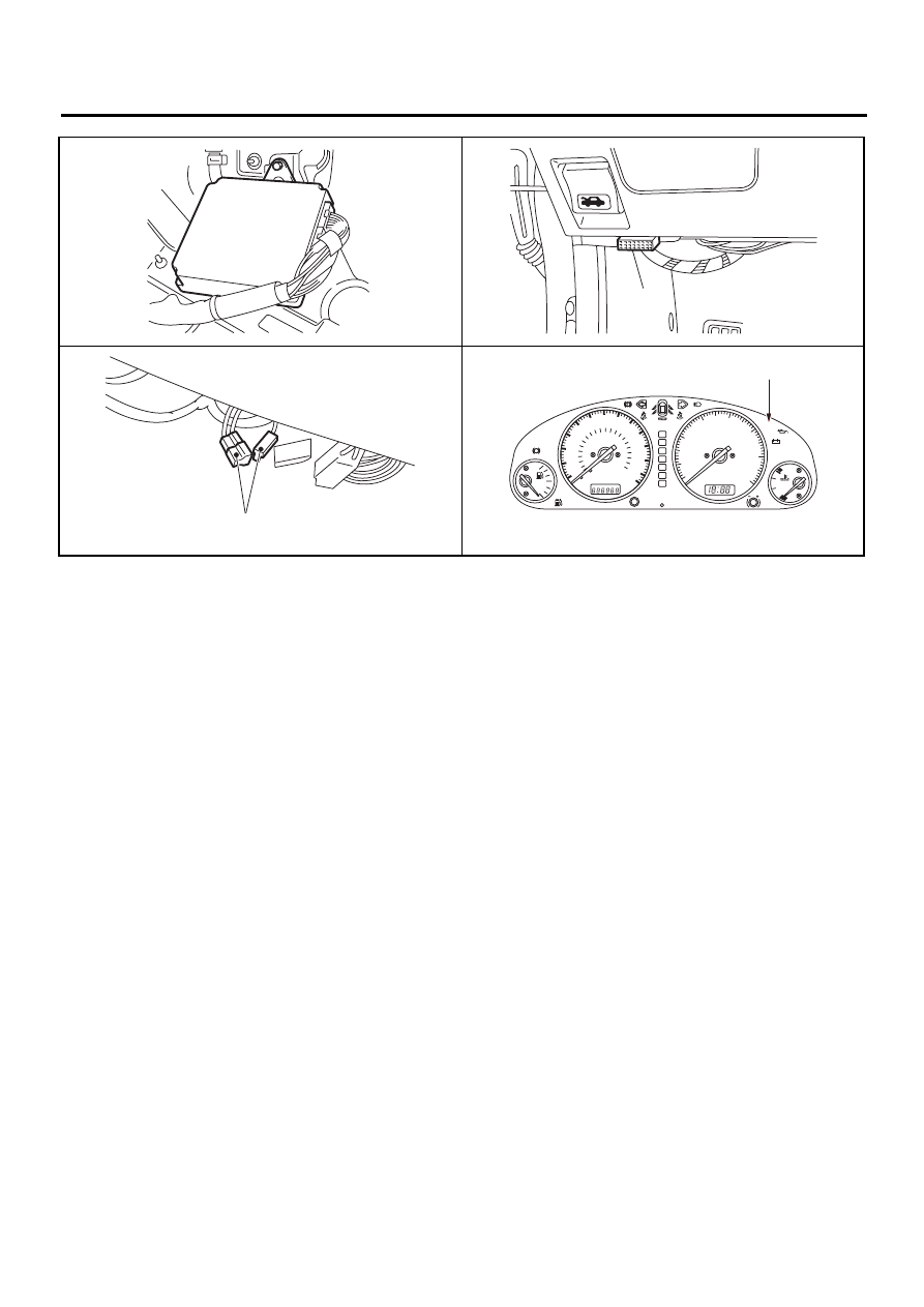
• MODULE
(1) Engine control module (ECM)
(3) Test mode connector
(2) Data link connector (for Subaru
Select Monitor and OBD-II general
scan tool)
(4) CHECK ENGINE malfunction indi-
cator lamp (MI)
EN-01103
( 1 )
( 4 )
( 3 )
( 2 )
EN-01104
( 1 )
( 3 )
( 2 )
( 4 )
EN(H4SO)-11
ENGINE (DIAGNOSTICS)
ELECTRICAL COMPONENTS LOCATION
EN-00845
( 1 )
EN-00846
( 2 )
EN-00847
( 3 )
( 4 )
EN-00848
1
1
2
3
4
5
6
H
C
7
0
2
3
D
N
R
P
CHECK
ENGINE
AT OIL
TEMP
FWD
x1000r/min
ABS
E
F
1/2
AIRBAG
0
20
40
60
80
100
120
140
km/h
MPH
20
40
60
80
100 120 140
160
180
200
220
TRIP
000
Нет комментариевНе стесняйтесь поделиться с нами вашим ценным мнением.
Текст