Subaru Legacy III (2000-2003 year). Service manual — part 348

EN(H6DO)-194
ENGINE (DIAGNOSTICS)
DIAGNOSTIC PROCEDURE WITH DIAGNOSTIC TROUBLE CODE (DTC)
9
CHECK INTAKE MANIFOLD PRESSURE
SENSOR.
1) Start the engine and warm-up engine until
coolant temperature is greater than 75
°
C
(167
°
F).
2) Place the shift lever in neutral position.
3) Turn A/C switch to OFF.
4) Turn all accessory switches to OFF.
5) Read data of intake manifold pressure sen-
sor signal using Subaru Select Monitor or
OBD-II general scan tool.
Is the measured value within the specified
range?
NOTE:
• Subaru Select Monitor
For detailed operation procedure, refer to the
“READ CURRENT DATA FOR ENGINE”.
<Ref. to EN(H6DO)-34, Subaru Select Moni-
tor.>
• OBD-II general scan tool
For detailed operation procedure, refer to the
OBD-II General Scan Tool Instruction Manual.
Ignition ON 73.3 — 106.6 kPa
(550 — 800 mmHg, 21.65 —
31.50 inHg), Idling 24.0 — 41.3
kPa (180 — 310 mmHg, 7.09
— 12.20 inHg)
Replace intake
manifold pressure
sensor. <Ref. to
FU(H6DO)-34,
Intake Manifold
Pressure Sensor.>
10
CHECK INTAKE AIR TEMPERATURE SEN-
SOR.
1) Start the engine and warm-up engine until
coolant temperature is greater than 75
°
C
(167
°
F).
2) Place the shift lever in neutral position.
3) Turn A/C switch to OFF.
4) Turn all accessory switches to OFF.
5) Open front hood.
6) Measure ambient temperature.
7) Read data of intake manifold pressure sen-
sor signal using Subaru Select Monitor or
OBD-II general scan tool.
Is value the specified range when ambient
temperature is subtracted from intake air
temperature?
NOTE:
• Subaru Select Monitor
For detailed operation procedure, refer to the
“READ CURRENT DATA FOR ENGINE”.
<Ref. to EN(H6DO)-34, Subaru Select Moni-
tor.>
• OBD-II general scan tool
For detailed operation procedure, refer to the
OBD-II General Scan Tool Instruction Manual.
−
10 — 50
°
C (14 — 122
°
F)
Contact SUBARU
distributor service.
NOTE:
Inspection by DTM
is required, be-
cause probable
cause is deteriora-
tion of multiple
parts.
Check intake air
temperature sen-
sor. <Ref. to
FU(H6DO)-35,
Intake Air Temper-
ature Sensor.>
Step
Value
Yes
No
EN(H6DO)-195
ENGINE (DIAGNOSTICS)
DIAGNOSTIC PROCEDURE WITH DIAGNOSTIC TROUBLE CODE (DTC)
MEMO:
EN(H6DO)-196
ENGINE (DIAGNOSTICS)
DIAGNOSTIC PROCEDURE WITH DIAGNOSTIC TROUBLE CODE (DTC)
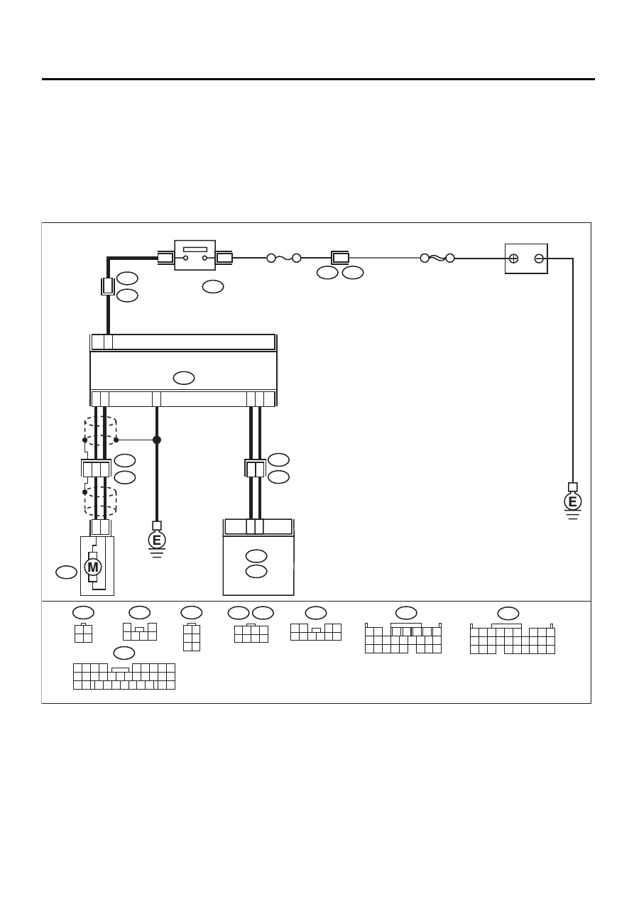
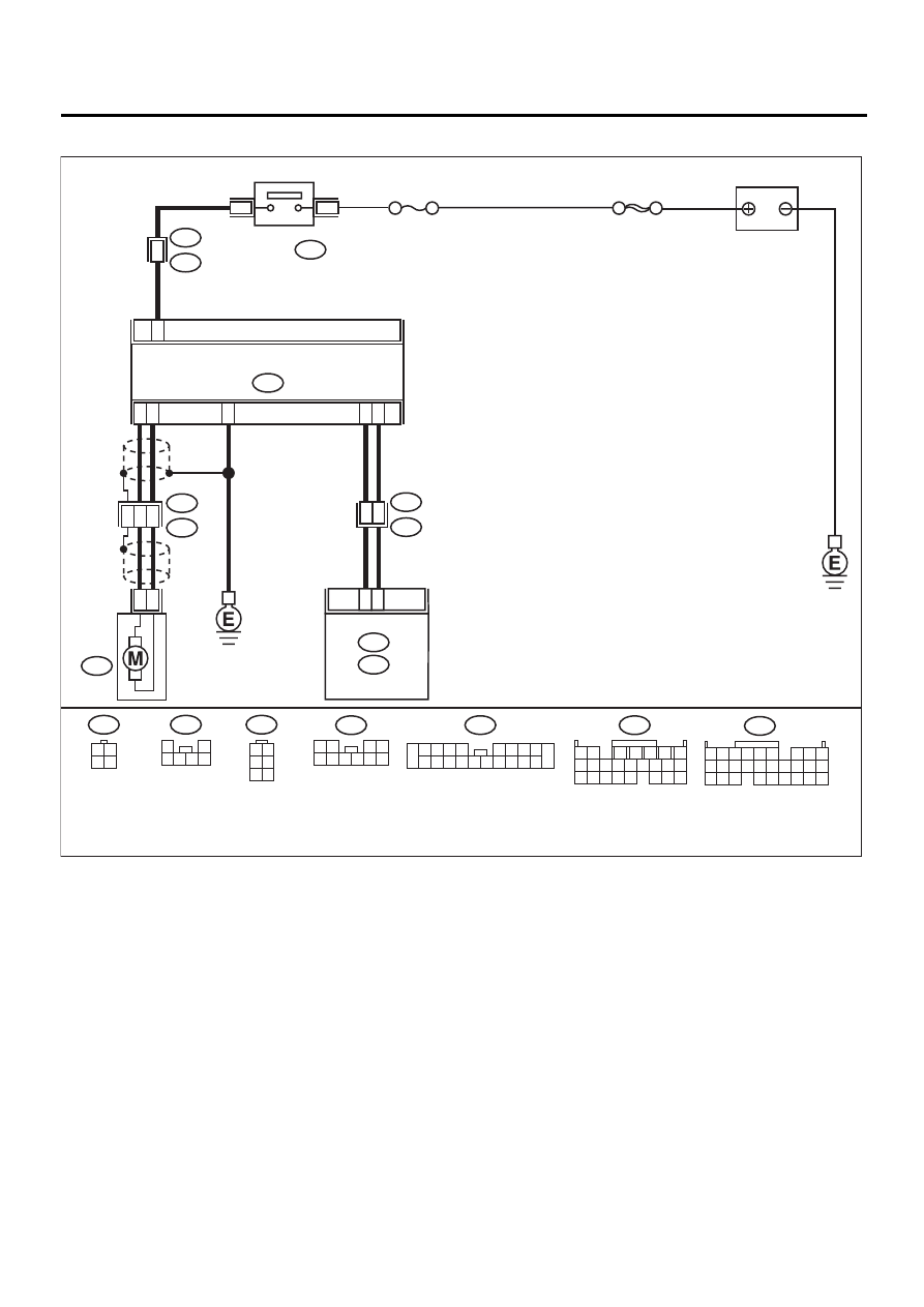
AI: DTC P0230 — FUEL PUMP PRIMARY CIRCUIT —
• DTC DETECTING CONDITION:
• Two consecutive driving cycles with fault
CAUTION:
After repair or replacement of faulty parts, conduct Clear Memory Mode <Ref. to EN(H6DO)-54, OP-
ERATION, Clear Memory Mode.> and Inspection Mode <Ref. to EN(H6DO)-47, Inspection Mode.>.
• WIRING DIAGRAM:
• LHD model
EN-01084
10
R57
R58
R15
9
BATTERY
FUEL PUMP
CONTROLLER
FUEL
PUMP
FUEL PUMP
RELAY
SBF-5
F44
B61
B97
B46
R1
6
3
R3
B99
2
4
R122
7
B136
C:
3
5
4
24
25
8
6
5
1 2
7
8 9
5
6
3
4
10 11 12
19 20 21
13 14 15 16
17 18
22 23 24
F44
B97
1 2 3 4
5 6 7 8
C16
ECM
B136
B12
C:
B135
B:
B135
B:
5 6
7 8
2
1
9
4
3
10
24
22
23
25
11 12 13 14 15
26 27 28
16 17 18 19
20 21
2
1
B46
3 4
1 2
R122
1 2
3 4
5 6 7 8 9 10
R57
1
2
3 4 5 6
R58
1 2
3 4
5 6
NO. 13
B99
21
9
32
1 2 3 4
5 6
10 11 12 13 14 15
7
16
23
30
19 20
22
26 27 28 29
8
17
24
31
18
25
EN(H6DO)-197
ENGINE (DIAGNOSTICS)
DIAGNOSTIC PROCEDURE WITH DIAGNOSTIC TROUBLE CODE (DTC)
• RHD model
EN-01085
10
R57
R58
R15
9
BATTERY
FUEL PUMP
CONTROLLER
FUEL
PUMP
FUEL PUMP
RELAY
SBF-5
B99
B46
R3
1
R2
B98
2
4
R122
7
B136
C:
3
5
4
14
16
8
6
5
1 2
7
8 9
5
6
3
4
10 11 12
19 20 21
13 14 15 16
17 18
22 23 24
C16
ECM
B136
B12
C:
B135
B:
B135
B:
5 6
7 8
2
1
9
4
3
10
24
22
23
25
11 12 13 14 15
26 27 28
16 17 18 19
20 21
2
1
B46
3 4
1 2
R122
1 2
3 4
5 6 7 8 9 10
R57
1
2
3 4 5 6
R58
1 2
3 4
5 6
NO. 13
R2
2 3 4 5
6 7 8 9
11 12 13 14
17 18 19 20
10
1
15 16
Нет комментариевНе стесняйтесь поделиться с нами вашим ценным мнением.
Текст