Subaru Legacy III (2000-2003 year). Service manual — part 834
PS-24
POWER ASSISTED SYSTEM (POWER STEERING)
STEERING WHEEL
2. Steering Wheel
A: REMOVAL
1) Disconnect ground cable from battery.
2) Set tires to straight-ahead position.
3) Remove airbag module. <Ref. to AB-12, RE-
MOVAL, Driver's Airbag Module.>
WARNING:
Always refer to “Airbag System” before per-
forming airbag module service (if so equipped).
<Ref. to AB-12, INSPECTION, Driver's Airbag
Module.>
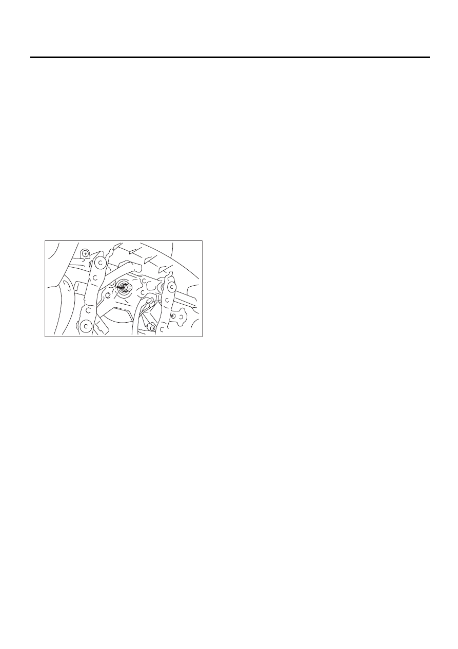
4) Remove steering wheel nut, and then draw out
steering wheel from shaft using steering puller.
NOTE:
Make matching marks on steering wheel and steer-
ing column in advance.
B: INSTALLATION
1) Align center of roll connector. <Ref. to AB-19,
ADJUSTMENT, Roll Connector.>
2) Install in the reverse order of removal.
NOTE:
Align matching marks on steering wheel and steer-
ing column.
Tightening torque:
4.5 N·m (4.5 kgf-m, 32.5 ft-lb)
Column cover-to-steering wheel clearance:
2 — 4 mm (0.08 — 0.16 in)
WARNING:
Always refer to “Airbag System” before per-
forming airbag module service (if so equipped).
<Ref. to AB-12, INSPECTION, Driver's Airbag
Module.>
CAUTION:
Insert roll connector guide pin into guide hole
on lower end of surface of steering wheel to
prevent damage. Draw out airbag system con-
nector, horn connector and cruise control con-
nectors from guide hole of steering wheel lower
end.
C: INSPECTION
1) Check steering wheel for deformation. If the de-
formation is excessive, replace steering wheel.
2) Check splines on steering wheel for damage. If
the damage is excessive, replace steering wheel.
(1) Matching mark
PS-00030
( 1 )
PS-25
POWER ASSISTED SYSTEM (POWER STEERING)
UNIVERSAL JOINT
3. Universal Joint
A: REMOVAL
1) Set the vehicle on a lift.
2) Remove the steering wheel. <Ref. to PS-24, RE-
MOVAL, Steering Wheel.>
3) Lift-up the vehicle.
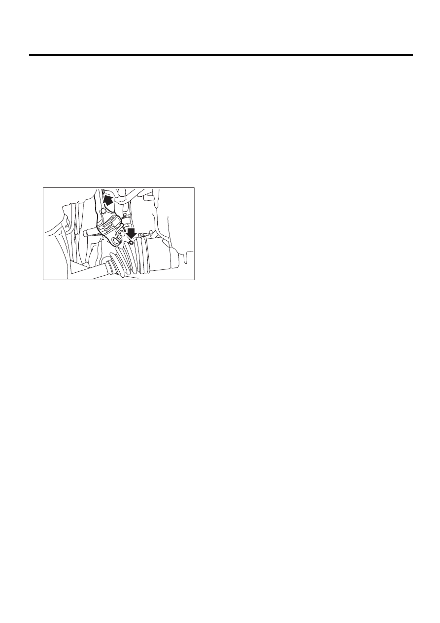
4) Remove universal joint bolts and then remove
universal joint.
CAUTION:
Scribe alignment marks on universal joint so
that it can be reassembled at the original serra-
tion.
B: INSTALLATION
1) Install universal joint.
(1) Align bolts hole on the long yoke side of uni-
versal joint with the cutout at the serrated sec-
tion of shaft end, and insert universal joint.
(2) Align bolt hole on the short yoke side of uni-
versal joint with the cutout at the serrated sec-
tion of gearbox assembly. Lower universal joint
completely.
(3) Temporarily tighten bolt on the short yoke
side. Raise universal joint to make sure the bolt
is properly passing through the cutout at the ser-
rated section.
(4) Tighten bolt on the long yoke, then that on
the short yoke side.
Tightening torque:
24 N·m (2.4 kgf-m, 17.4 ft-lb)
CAUTION:
• Make sure that universal joint bolt is tight-
ened through notch in shaft serration.
• Excessively large tightening torque of uni-
versal joint bolts may lead to heavy steering
wheel operation.
Standard clearance between gearbox to DOJ:
Over 15 mm (0.59 in)
2) Lower the vehicle.
3) Align center of roll connector. <Ref. to AB-19,
ADJUSTMENT, Roll Connector.>
CAUTION:
Ensure that front wheel are set straight forward
direction.
4) Install steering wheel and airbag module. <Ref.
to PS-24, INSTALLATION, Steering Wheel.>
WARNING:
Always refer to “Airbag System” before per-
forming airbag module service (if so equipped).
<Ref. to AB-12, INSPECTION, Driver's Airbag
Module.> and <Ref. to AB-12, INSTALLATION,
Driver's Airbag Module.>
PS-00031
PS-26
POWER ASSISTED SYSTEM (POWER STEERING)
UNIVERSAL JOINT
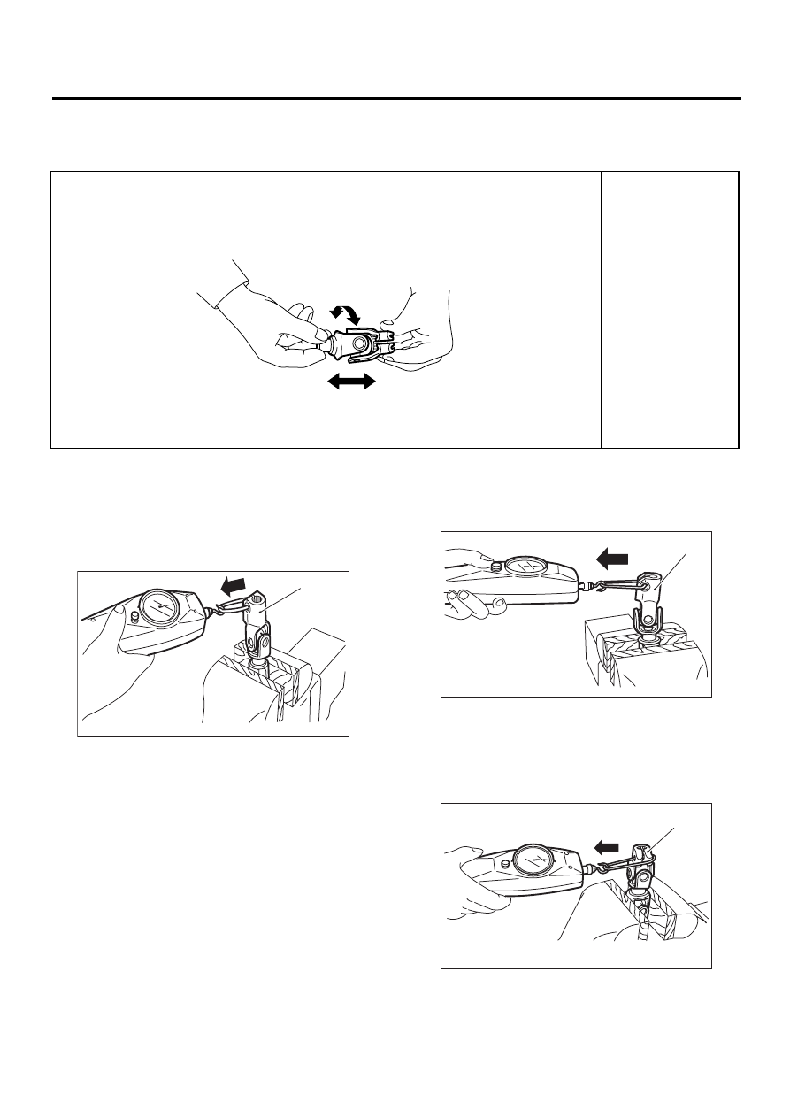
C: INSPECTION
Clean the disassembled parts with a cloth, and check for wear, damage, or any other faults. If necessary, re-
pair or replace faulty parts.
Measurement of folding torque of universal joint is
as shown in the figures.
Service limit:
Maximum load; 5.49 N (0.56 kgf, 1.23 lb) or
less
Service limit:
Maximum load; 5.49 N (0.56 kgf, 1.23 lb) or
less
Service limit:
Maximum load; 8.43 N (0.86 kgf, 1.90 lb) or
less
Inspection
Corrective action
(1) Free play
(2) Swinging torque
Yawing torque
Looseness
Standard value of universal joint free play: 0 mm (0 in)
Max. value of universal joint swinging torque: 0.3 N·m (0.03 kgf-m, 0.2 ft-lb)
Replace if faulty.
(1)
(2)
PS-00274
(1) Long yoke
PS-00034
( 1 )
(1) Long yoke
(1) Short yoke
PS-00035
( 1 )
PS-00036
( 1 )
PS-27
POWER ASSISTED SYSTEM (POWER STEERING)
UNIVERSAL JOINT
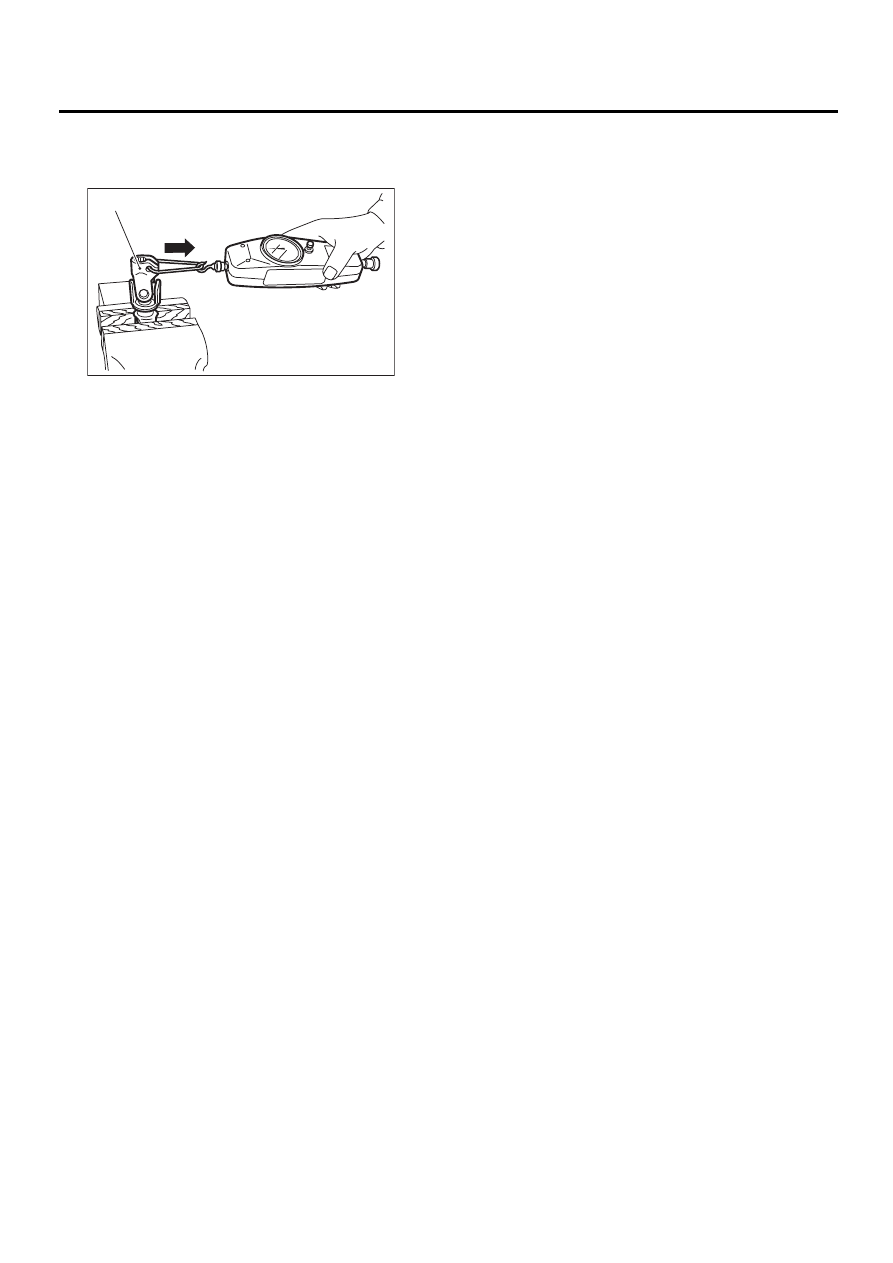
Service limit:
Maximum load; 8.43 N (0.86 kgf, 1.90 lb) or
less
(1) Short yoke
PS-00037
( 1 )
Нет комментариевНе стесняйтесь поделиться с нами вашим ценным мнением.
Текст