Subaru Legacy III (2000-2003 year). Service manual — part 330

EN(H6DO)-122
ENGINE (DIAGNOSTICS)
DIAGNOSTIC PROCEDURE WITH DIAGNOSTIC TROUBLE CODE (DTC)
Step
Value
Yes
No
1
CHECK OUTPUT SIGNAL FROM ECM.
1) Turn ignition switch to ON.
2) Measure voltage between ECM connector
and chassis ground.
Connector & terminal
(B137) No. 6 (+) — Chassis ground (
−−−−
):
Does the measured value exceed the spec-
ified value?
8 V
2
CHECK OUTPUT SIGNAL FROM ECM.
Measure voltage between ECM connector and
chassis ground.
Connector & terminal
(B137) No. 7 (+) — Chassis ground (
−−−−
):
Does the measured value exceed the specified
value?
8 V
3
CHECK FRONT OXYGEN (A/F) SENSOR
HEATER CURRENT.
1) Turn ignition switch to OFF.
2) Repair battery short circuit in harness
between ECM and front oxygen (A/F) sen-
sor connector.
3) Turn ignition switch to ON.
4) Read data of front oxygen (A/F) sensor
heater current using Subaru Select Monitor
or the OBD-II general scan tool.
Does the measured value exceed the spec-
ified value?
NOTE:
• Subaru Select Monitor
For detailed operation procedure, refer to the
“READ CURRENT DATA FOR ENGINE”.
<Ref. to EN(H6DO)-34, Subaru Select Moni-
tor.>
• OBD-II general scan tool
For detailed operation procedure, refer to the
OBD-II General Scan Tool Instruction Manual.
2.3 A
Replace ECM.
<Ref. to
FU(H6DO)-46,
Engine Control
Module.>
END
4
CHECK OUTPUT SIGNAL FROM ECM.
Measure voltage between ECM connector and
chassis ground.
Connector & terminal
(B137) No. 6 (+) — Chassis ground (
−−−−
):
Does the voltage change more than the speci-
fied value shaking harness and connector of
ECM while monitoring the value with voltage
meter?
8 V
Repair battery
short circuit in har-
ness between
ECM and front
oxygen (A/F) sen-
sor connector.
5
CHECK OUTPUT SIGNAL FROM ECM.
Measure voltage between ECM connector and
chassis ground.
Connector & terminal
(B137) No. 7 (+) — Chassis ground (
−−−−
):
Does the voltage change more than the speci-
fied value by shaking harness and connector
of ECM while monitoring the value with voltage
meter?
8 V
Repair battery
short circuit in har-
ness between
ECM and front
oxygen (A/F) sen-
sor connector.
END
EN(H6DO)-123
ENGINE (DIAGNOSTICS)
DIAGNOSTIC PROCEDURE WITH DIAGNOSTIC TROUBLE CODE (DTC)
MEMO:
EN(H6DO)-124
ENGINE (DIAGNOSTICS)
DIAGNOSTIC PROCEDURE WITH DIAGNOSTIC TROUBLE CODE (DTC)
I:
DTC P0068 — MANIFOLD ABSOLUTE PRESSURE/BAROMETRIC PRES-
SURE CIRCUIT RANGE/PERFORMANCE —
• DTC DETECTING CONDITION:
• Two consecutive driving cycles with fault
• TROUBLE SYMPTOM
• Erroneous idling
CAUTION:
After repair or replacement of faulty parts, conduct Clear Memory Mode <Ref. to EN(H6DO)-54, OP-
ERATION, Clear Memory Mode.> and Inspection Mode <Ref. to EN(H6DO)-47, OPERATION, Inspec-
tion Mode.>.
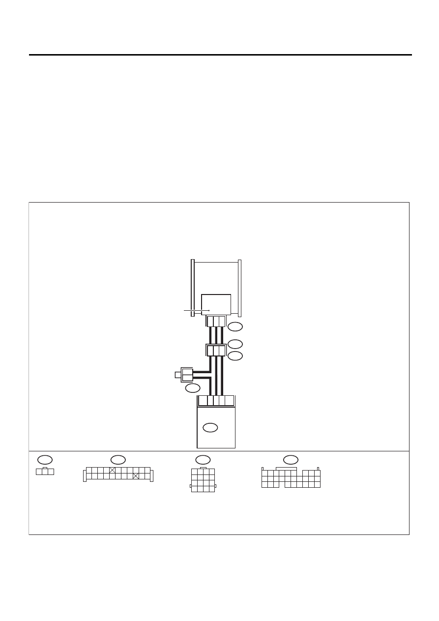
• WIRING DIAGRAM:
EN-00811
9
19
8
5
8
B135
B20
E1
16
13
14
B83
E21
1 2 3
B83
B20
B135
ECM
3
2
1
E21
INTAKE MANIFOLD
PRESSURE SENSOR
THROTTLE BODY
5 6
7 8
2
1
9
4
3
10
24
22
23
25
11 12 13 14 15
26 27 28
16 17 18 19
20 21
1 2 3 4
5 6 7 8
9 10 11 12
13 14 15 16
1 2 3 4
5 6 7 8 9 10
11 12
19 20
13 14 15 16 17 18

EN(H6DO)-125
ENGINE (DIAGNOSTICS)
DIAGNOSTIC PROCEDURE WITH DIAGNOSTIC TROUBLE CODE (DTC)
Step
Value
Yes
No
1
CHECK IDLE SWITCH SIGNAL.
1) Turn ignition switch to ON.
2) Operate the LED operation mode for
engine using Subaru Select Monitor.
Does the LED of {Idle Switch Signal} come
on?
NOTE:
• Subaru Select Monitor
For detailed operation procedure, refer to the
“LED OPERATION MODE FOR ENGINE”.
<Ref. to EN(H6DO)-34, Subaru Select Moni-
tor.>
LED comes on.
Check throttle
position sensor cir-
cuit. <Ref. to
EN(H6DO)-148,
DTC P0121 —
THROTTLE/
PEDAL POSI-
TION SENSOR/
SWITCH “A” CIR-
CUIT RANGE/
PERFORMANCE
—, Diagnostic Pro-
cedure with Diag-
nostic Trouble
Code (DTC).>
NOTE:
In this case, it is
not necessary to
inspect DTC
P0106.
2
CHECK ANY OTHER DTC ON DISPLAY.
Is any other DTC displayed?
Another DTC is displayed.
Inspect the rele-
vant DTC using
“List of Diagnostic
Trouble Code
(DTC)”. <Ref. to
EN(H6DO)-89, List
of Diagnostic
Trouble Code
(DTC).>
NOTE:
In this case, it is
not necessary to
inspect DTC
P0106.
3
CHECK CONDITION OF INTAKE MANIFOLD
PRESSURE SENSOR.
Is the intake manifold pressure sensor installa-
tion bolt tightened securely?
Tightened securely.
Tighten intake
manifold pressure
sensor installation
bolt securely.
4
CHECK CONDITION OF THROTTLE BODY.
Is the throttle body installation bolt tightened
securely?
Tightened securely.
Tighten throttle
body installation
bolt securely.
5
CHECK CONDITION OF EGR VALVE.
Is there any foreign object caught between
EGR solenoid valve and intake manifold?
There is a foreign object.
Completely
remove foreign
object, and install
EGR solenoid
valve securely to
the intake mani-
fold.
Replace intake
manifold pressure
sensor. <Ref. to
FU(H6DO)-34,
Intake Manifold
Pressure Sensor.>
Нет комментариевНе стесняйтесь поделиться с нами вашим ценным мнением.
Текст