Subaru Legacy III (2000-2003 year). Service manual — part 636
MT-112
MANUAL TRANSMISSION AND DIFFERENTIAL
GENERAL DIAGNOSTIC
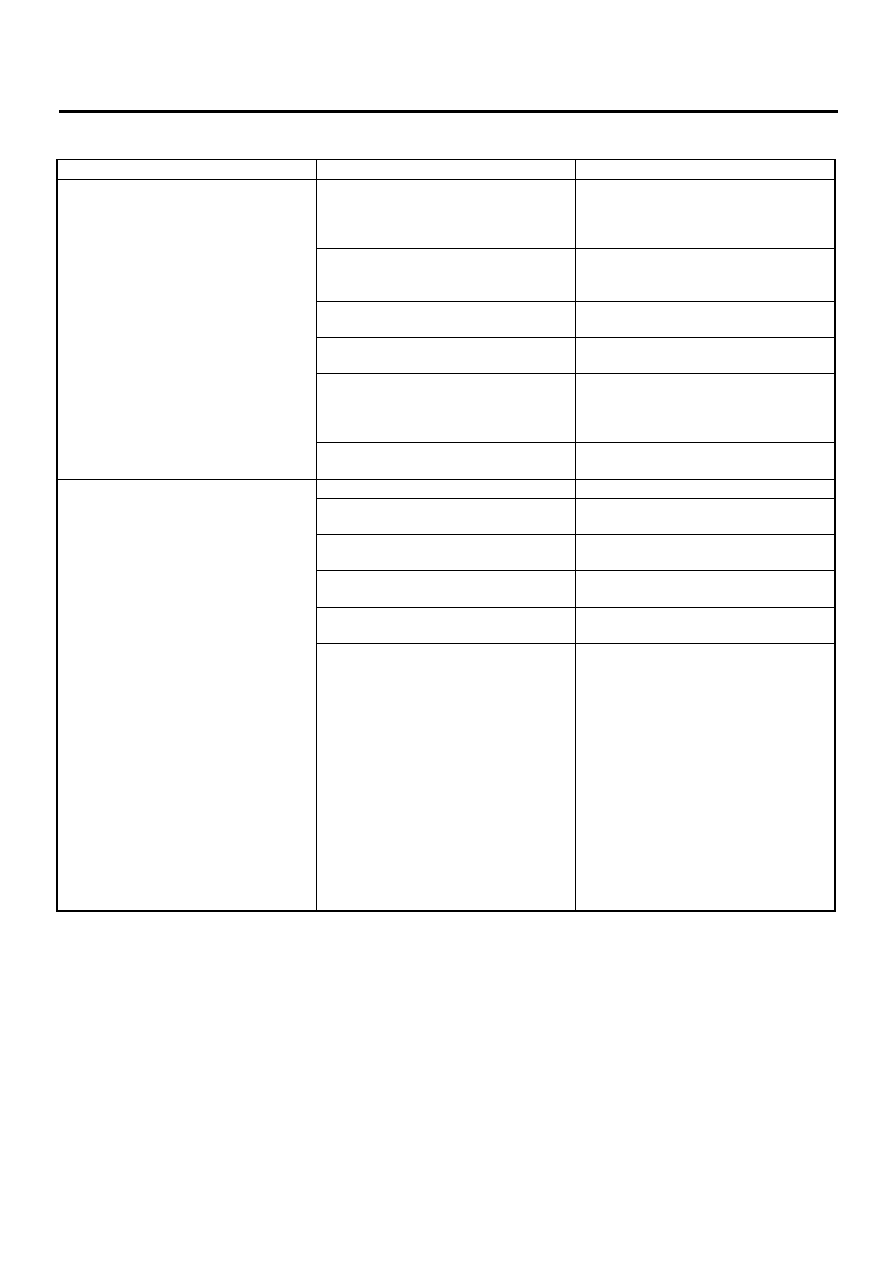
2. DIFFERENTIAL
Symptom
Possible cause
Remedy
1. Broken differential (case, gear, bear-
ing, etc.)
NOTE:
Abnormal noise will develop and finally it
will become impossible to continue to run
due to broken pieces obstructing the gear
revolution.
(a) Insufficient or improper oil
Disassemble differential and replace bro-
ken components and at the same time
check other components for any trouble,
and replace if necessary.
(b) Use of vehicle under severe condi-
tions such as excessive load and
improper use of clutch
Readjust bearing preload and backlash
and face contact of gears.
(c) Improper adjustment of taper roller
bearing
Adjust.
(d) Improper adjustment of drive pinion
and hypoid driven gear
Adjust.
(e) Excessive backlash due to worn dif-
ferential side gear, washer or differential
pinion vehicle under severe operating
conditions.
Add recommended oil to specified level.
Do not use vehicle under severe operat-
ing conditions.
(f) Loose hypoid driven gear clamping
bolts
Tighten.
2. Differential and hypoid gear noises
Troubles of the differential and hypoid
gear always appear as noise problems.
Therefore noise is the first indication of
the trouble. However noises from the
engine, muffler, tire, exhaust gas, bear-
ing, body, etc. are easily mistaken for the
differential noise. Pay special attention to
the hypoid gear noise because it is easily
confused with other gear noises. There
are the following four kinds of noises.
• Gear noise when driving: If noise
increases as vehicle speed increases it
may be due to insufficient gear oil, incor-
rect gear engagement, damaged gears,
etc.
• Gear noise when coasting: Damaged
gears due to maladjusted bearings and
incorrect shim adjustment
• Bearing noise when driving or when
coasting: Cracked, broken or damaged
bearings
• Noise which mainly occurs when turn-
ing: Unusual noise from differential side
gear, differential pinion, differential pin-
ion shaft, etc.
(a) Insufficient oil
Lubricate.
(b) Improper adjustment of hypoid driven
gear and drive pinion
Check tooth contact.
(c) Worn teeth of hypoid driven gear and
drive pinion
Replace as a set.
Readjust bearing preload.
(d) Loose roller bearing
Readjust hypoid driven gear to drive pin-
ion backlash and check tooth contact.
(e) Distorted hypoid driven gear or differ-
ential case
Replace.
(f) Worn washer and differential pinion
shaft
Replace.

CLUTCH SYSTEM
CL
Page
General Description . . . . . . . . . . . . . . . . . . . . . 2
Clutch Disc and Cover . . . . . . . . . . . . . . . . . . . ..15
Flywheel . . . . . . . . . . . . . . . . . . . . . . . . . 20
Release Bearing and Lever. . . . . . . . . . . . . . . . . ...22
Operating Cylinder . . . . . . . . . . . . . . . . . . . . . 25
Master Cylinder . . . . . . . . . . . . . . . . . . . . . . .27
Clutch Pipe and Hose . . . . . . . . . . . . . . . . . . . ...29
Clutch Fluid . . . . . . . . . . . . . . . . . . . . . . . ...30
Clutch Fluid Air Bleeding. . . . . . . . . . . . . . . . . . ...31
Clutch Pedal. . . . . . . . . . . . . . . . . . . . . . . ..33
Clutch Switch . . . . . . . . . . . . . . . . . . . . . . . 40
General Diagnostic Table. . . . . . . . . . . . . . . . . . ..41
CL-2
CLUTCH SYSTEM
GENERAL DESCRIPTION
1. General Description
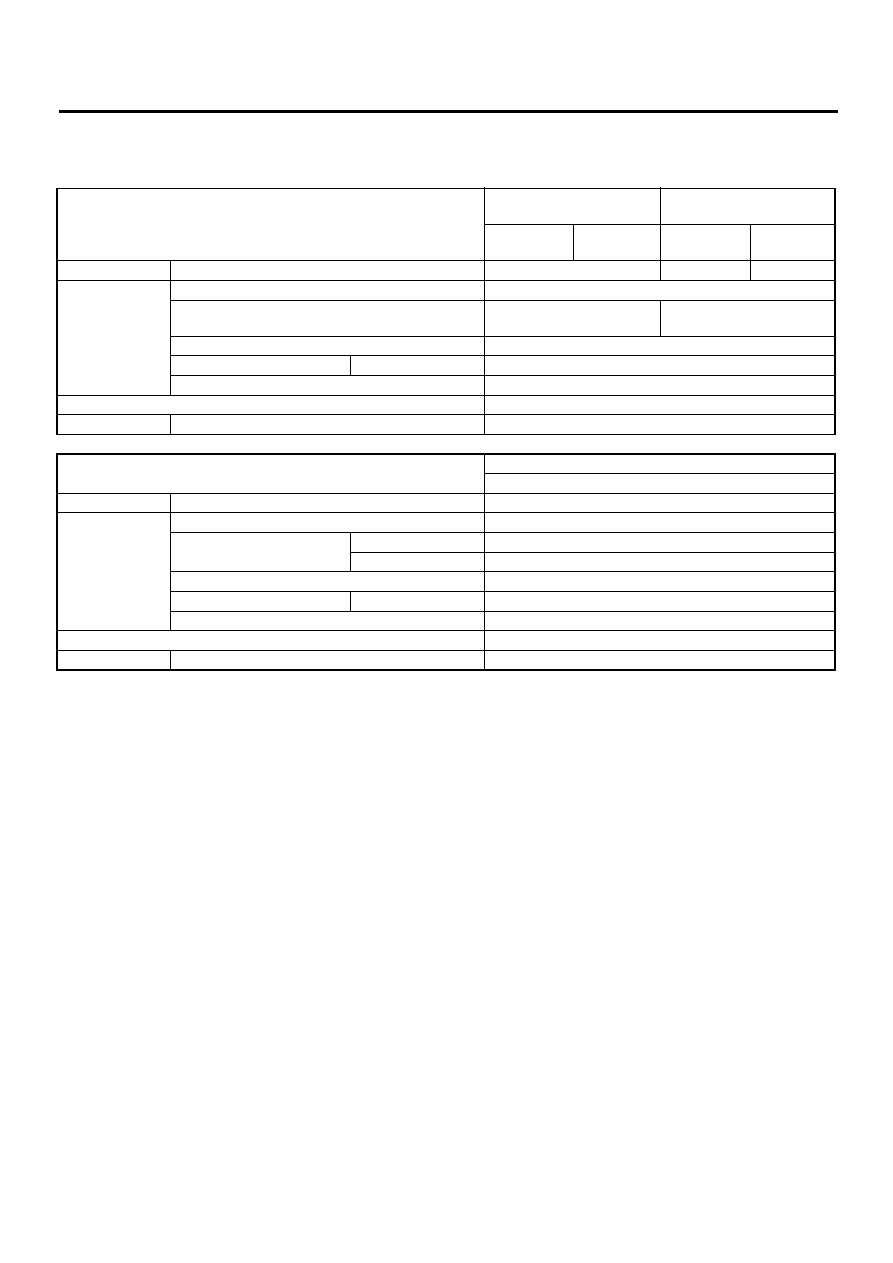
A: SPECIFICATIONS
Model
Europe and Australia
Except Europe and Austra-
lia
2.0 L Non-
Turbo
2.5 L
2.0 L Non-
Turbo
2.5 L
Clutch cover
Diaphragm set load
kgf (lb)
550 (1,213)
450 (992)
580 (1,279)
Clutch disc
Facing material
Woven
O.D.
×
I.D.
×
thickness
mm (in)
228.6
×
155
×
2.95
(9.00
×
6.10
×
0.1161)
225
×
150
×
3.5
(8.86
×
5.91
×
0.138)
Spline O.D.
mm (in)
25.2 (0.992)
Depth of rivet head mm (in)
Wear limit
0.3 (0.012)
Limit for deflection
mm (in)
1.0 (0.039) at R = 107 (4.21)
Clutch release lever ratio
1.6
Clutch pedal
Full stroke
mm (in)
130 — 135 (5.12 — 5.31)
Model
Australia
2.0 L Turbo
Clutch cover
Diaphragm set load
kgf (lb)
830 (1,830)
Clutch disc
Facing material
Woven
O.D.
×
I.D.
×
thickness
mm (in)
Flywheel side
230
×
150
×
3.2 (9.06
×
5.91
×
0.126)
Pressure plate side
230
×
150
×
3.5 (9.06
×
5.91
×
0.138)
Spline O.D.
mm (in)
25.2 (0.992)
Depth of rivet head mm (in)
Wear limit
0.3 (0.012)
Limit for deflection
mm (in)
0.8 (0.031) at R = 110 (4.33)
Clutch release lever ratio
1.7
Clutch pedal
Full stroke
mm (in)
130 — 135 (5.12 — 5.31)
CL-3
CLUTCH SYSTEM
GENERAL DESCRIPTION
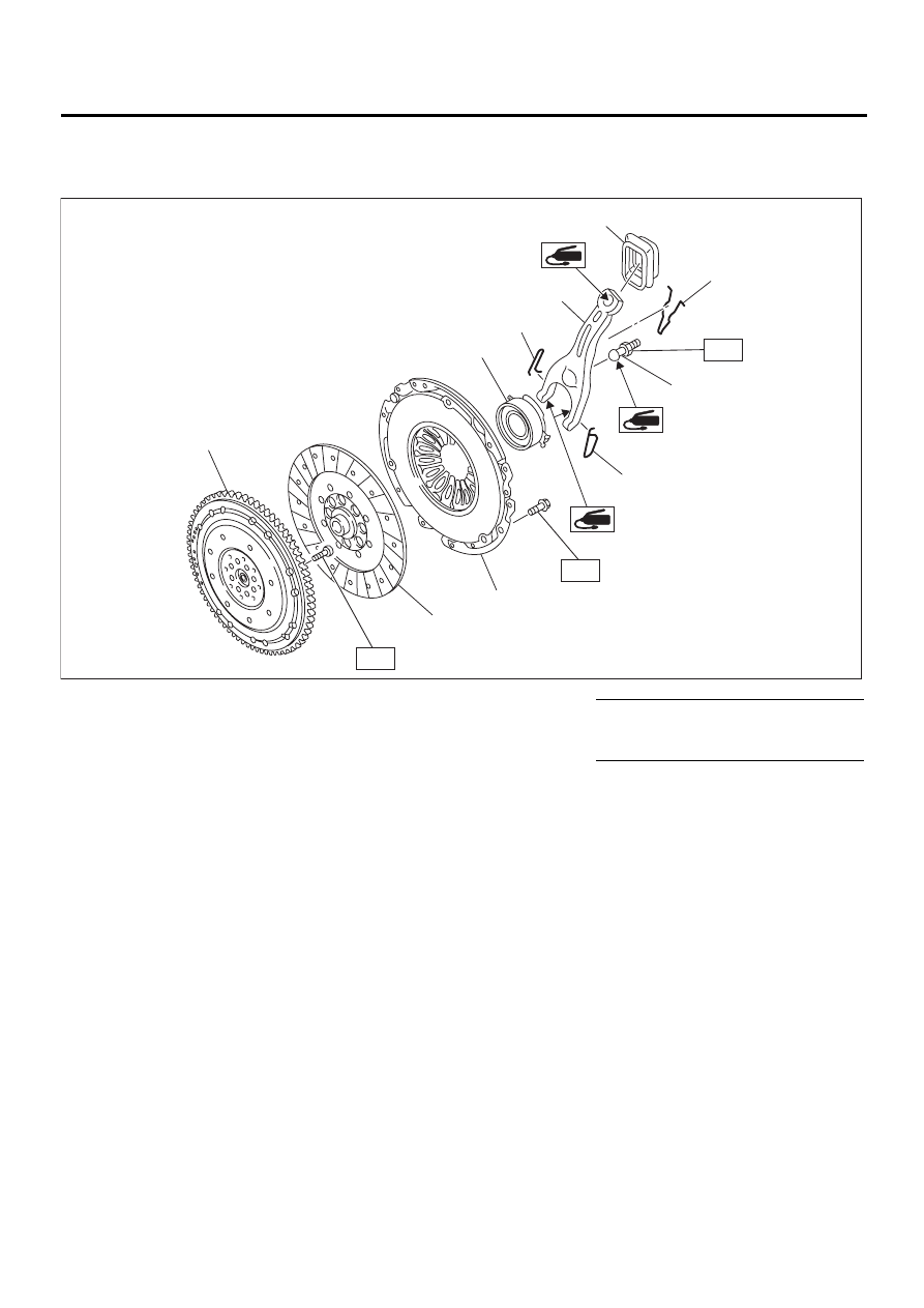
B: COMPONENT
1. CLUTCH ASSEMBLY FOR EUROPE AND AUSTRALIA NON-TURBO MODELS
(1) Clutch release lever seal
(6) Release bearing
Tightening torque: N·m (kgf-m, ft-lb)
(2) Retainer spring
(7) Clutch cover
T1: 15.7 (1.6, 11.6)
(3) Pivot
(8) Clutch disc
T2: 72 (7.3, 52.8)
(4) Release lever
(9) Dual mass flywheel
(5) Clip
CL-00170
( 1 )
( 2 )
( 3 )
( 4 )
( 5 )
( 5 )
( 6 )
( 7 )
( 8 )
( 9 )
T1
T2
T1
Нет комментариевНе стесняйтесь поделиться с нами вашим ценным мнением.
Текст