Subaru Legacy III (2000-2003 year). Service manual — part 590

AT-94
AUTOMATIC TRANSMISSION (DIAGNOSTICS)
DIAGNOSTIC PROCEDURE WITH DIAGNOSTIC TROUBLE CODE (DTC)
7
CHECK OUTPUT SIGNAL EMITTED FROM
TCM USING SUBARU SELECT MONITOR.
1) Connect all connectors.
2) Connect Subaru Select Monitor to data link
connector.
3) Start the engine, and turn Subaru Select
Monitor switch to ON.
4) Warm-up the transmission until ATF tem-
perature is above 80
°
C (176
°
F).
NOTE:
If ambient temperature is below 0
°
C (32
°
F),
drive the vehicle until the ATF reaches its oper-
ating temperature.
5) Stop the engine and turn ignition switch to
ON (engine OFF).
6) Move select lever to “N”.
7) Read data of 2-4 brake duty solenoid using
Subaru Select Monitor.
•2-4 brake duty solenoid is indicated in “%”.
8) Throttle is fully closed.
Is 2-4 brake duty solenoid data within the
specified value?
100%
8
CHECK OUTPUT SIGNAL EMITTED FROM
TCM USING SUBARU SELECT MONITOR.
1) Turn ignition switch to ON (Engine OFF).
2) Throttle is fully open.
3) Read line pressure duty solenoid data
using Subaru Select Monitor.
Is line pressure duty solenoid data less
than the specified value?
25%
Even if “POWER”
indicator lights up,
the circuit has
returned to a nor-
mal condition at
this time. A tempo-
rary poor contact
of the connector or
harness may be
the cause. Repair
harness or con-
nector in TCM and
transmission.
9
CHECK POOR CONTACT.
Is there poor contact in 2-4 brake duty solenoid
circuit?
There is poor contact.
Repair poor con-
tact.
Replace TCM.
<Ref. to AT-76,
Transmission Con-
trol Module
(TCM).>
10
CHECK 2-4 BRAKE DUTY SOLENOID (IN
TRANSMISSION).
1) Remove transmission connector from
bracket.
2) Drain automatic transmission fluid.
CAUTION:
Do not drain the automatic transmission flu-
id until it cools down.
3) Remove oil pan, and disconnect connector
from 2-4 brake duty solenoid.
4) Measure resistance between 2-4 brake
duty solenoid connector and transmission
ground.
Terminal
No. 1 — Transmission ground:
Is the measured value within the specified
range?
2.0 — 4.5
Ω
Replace 2-4 brake
duty solenoid.
<Ref. to AT-67,
Shift Solenoids,
Duty Solenoids
and ATF Temper-
ature Sensor.>
Step
Value
Yes
No

AT-95
AUTOMATIC TRANSMISSION (DIAGNOSTICS)
DIAGNOSTIC PROCEDURE WITH DIAGNOSTIC TROUBLE CODE (DTC)
11
CHECK HARNESS CONNECTOR BETWEEN
TRANSMISSION AND 2-4 BRAKE DUTY SO-
LENOID.
Measure resistance of harness between 2-4
brake duty solenoid and transmission connec-
tor.
Connector & terminal
(T4) No. 9 — (AT7) No. 1:
Is the measured value less than the specified
value?
1
Ω
Repair open circuit
in harness
between 2-4 brake
duty solenoid and
transmission con-
nector.
12
CHECK HARNESS CONNECTOR BETWEEN
TRANSMISSION AND 2-4 BRAKE DUTY SO-
LENOID.
Measure resistance of harness between trans-
mission connector and transmission ground.
Connector & terminal
(T4) No. 9 — Transmission ground:
Does the measured value exceed the specified
value?
1 M
Ω
Even if “POWER”
indicator lights up,
the circuit has
returned to a nor-
mal condition at
this time. A tempo-
rary poor contact
of the connector or
harness may be
the cause. Repair
harness or con-
nector in line pres-
sure duty solenoid
and transmission.
Repair short circuit
in harness
between 2-4 brake
duty solenoid and
transmission con-
nector.
Step
Value
Yes
No
AT-96
AUTOMATIC TRANSMISSION (DIAGNOSTICS)
DIAGNOSTIC PROCEDURE WITH DIAGNOSTIC TROUBLE CODE (DTC)
O: DTC 77 LOCK-UP DUTY SOLENOID
DIAGNOSIS:
Output signal circuit of lock-up duty solenoid is open or shorted.
TROUBLE SYMPTOM:
No “lock-up” (after engine warm-up).
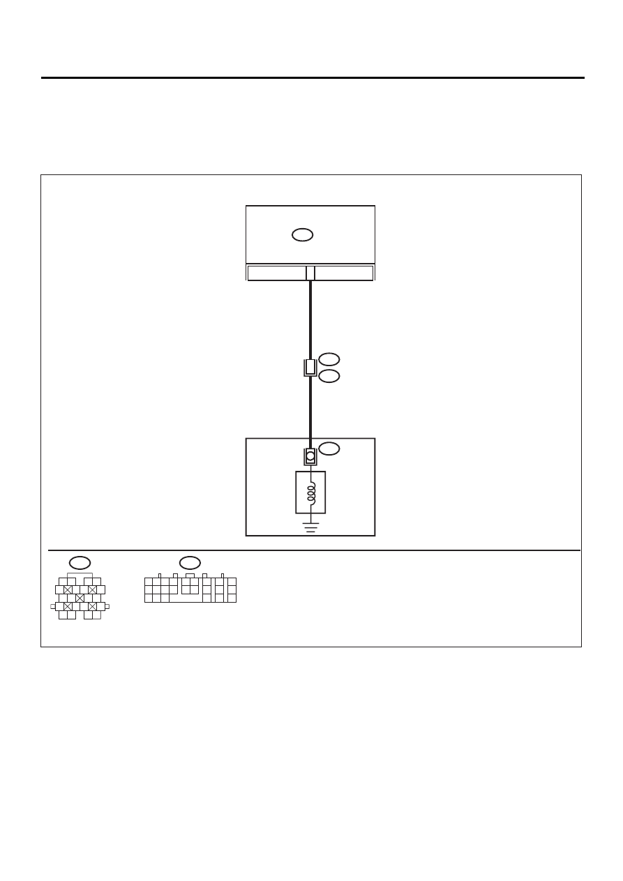
WIRING DIAGRAM:
AT-00589
7
TRANSMISSION
B54
TCM
AT3
13
T4
B11
LOCK-UP
DUTY
SOLENOID
B54
1 2
7
8
9
5 6
3 4
10 11 12
19 20 21
13
14 15
16
17
18
22
23
24
B11
1 2
5
6 7
8
13
14 15
16
9 10
11 12
3 4
17 18
19 20

AT-97
AUTOMATIC TRANSMISSION (DIAGNOSTICS)
DIAGNOSTIC PROCEDURE WITH DIAGNOSTIC TROUBLE CODE (DTC)
Step
Value
Yes
No
1
CHECK DTC.
Do multiple trouble codes appear in the on-
board diagnostics test mode?
DTC is displayed.
Go to another
Diagnostic trouble
code (DTC).
2
CHECK HARNESS CONNECTOR BETWEEN
TCM AND TRANSMISSION.
1) Turn ignition switch to OFF.
2) Disconnect connector from TCM and trans-
mission.
3) Measure resistance of harness between
TCM and transmission connector.
Connector & terminal
(B54) No. 7 — (B11) No. 13:
Is the measured value less than the speci-
fied value?
1
Ω
Repair open circuit
in harness
between TCM and
transmission con-
nector.
3
CHECK HARNESS CONNECTOR BETWEEN
TCM AND TRANSMISSION.
Measure resistance of harness connector
between TCM and chassis ground.
Connector & terminal
(B54) No. 7 — Chassis ground:
Does the measured value exceed the specified
value?
1 M
Ω
Repair short circuit
in harness
between TCM and
transmission con-
nector.
4
CHECK LOCK-UP DUTY SOLENOID.
Measure resistance between transmission
connector receptacle's terminals.
Connector & terminal
(T4) No. 13 — No. 16:
Is the measured value within the specified
range?
10 — 17
Ω
5
PREPARE SUBARU SELECT MONITOR.
Do you have a Subaru Select Monitor?
Subaru Select Monitor is avail-
able.
Нет комментариевНе стесняйтесь поделиться с нами вашим ценным мнением.
Текст