Subaru Legacy III (2000-2003 year). Service manual — part 107

EN(H4SO)-40
ENGINE (DIAGNOSTICS)
INSPECTION MODE
12.Inspection Mode
A: OPERATION
Carry out trouble diagnosis shown in the following DTC table.
When performing trouble diagnosis which is not shown in the DTC table, refer to the next item Drive cycle.
<Ref. to EN(H4SO)-45, Drive Cycle.>
DTC No.
Item
P0031
HO2S Heater control circuit low (Bank 1 Sensor 1)
P0032
HO2S Heater control circuit high (Bank 1 Sensor 1)
P0037
HO2S Heater control circuit low (Bank 1 Sensor 2)
P0038
HO2S Heater control circuit high (Bank 1 Sensor 2)
P0068
Manifold absolute pressure/barometric pressure circuit range/performance
P0107
Manifold absolute pressure/barometric pressure circuit low input
P0108
Manifold absolute pressure/barometric pressure circuit high input
P0112
Intake air temperature circuit low input
P0113
Intake air temperature circuit high input
P0117
Engine coolant temperature circuit low input
P0118
Engine coolant temperature circuit high input
P0122
Throttle/pedal position sensor/switch “A” circuit low input
P0123
Throttle/pedal position sensor/switch “A” circuit high input
P0129
Barometric pressure too low
P0131
O2 sensor circuit low voltage (Bank 1 Sensor 1)
P0132
O2 sensor circuit high voltage (Bank 1 Sensor 1)
P0134
O2 sensor circuit no activity detected (Bank 1 Sensor 1)
P0137
O2 sensor circuit low voltage (Bank 1 Sensor 2)
P0138
O2 sensor circuit high voltage (Bank 1 Sensor 2)
P0327
Knock sensor 1 circuit low input (Bank 1 or Single sensor)
P0328
Knock sensor 1 circuit high input (Bank 1 or Single sensor)
P0335
Crankshaft position sensor “A” circuit
P0336
Crankshaft position sensor “A” circuit range/performance
P0340
Camshaft position sensor “A” circuit (Bank 1 or Single sensor)
P0341
Camshaft position sensor “A” circuit range/performance (Bank 1 or Single sensor)
P0458
Evaporative emission control system purge control valve circuit low
P0462
Fuel level sensor circuit low input
P0463
Fuel level sensor circuit high input
P0502
Vehicle speed sensor circuit low input
P0503
Vehicle speed sensor intermittent/erratic/high
P0512
Starter request circuit
P0513
Incorrect immobilizer key
P0519
Idle air control circuit system performance
P0565
Cruise control on signal
P0604
Internal control module random access memory (RAM) error
P0691
Cooling fan 1 control circuit low
P0692
Cooling fan 1 control circuit high
P0703
Torque converter/brake switch “B” circuit
P0705
Transmission range sensor circuit (PRNDL input)
P0710
Transmission fluid temperature sensor circuit
P0716
Input/turbine speed sensor circuit range/performance
P0720
Output speed sensor circuit
P0726
Engine speed input circuit range/performance
P0731
Gear 1 incorrect ratio
P0732
Gear 2 incorrect ratio

EN(H4SO)-41
ENGINE (DIAGNOSTICS)
INSPECTION MODE
P0733
Gear 3 incorrect ratio
P0734
Gear 4 incorrect ratio
P0741
Torque converter clutch circuit performance or stuck off
P0743
Torque converter clutch circuit electrical
P0748
Pressure control solenoid “A” electrical
P0753
Shift solenoid “A” electrical
P0758
Shift solenoid “B” electrical
P0771
Shift solenoid “E” performance or stuck off
P0778
Pressure control solenoid “B” electrical
P0785
Shift/timing solenoid
P0851
Neutral switch input circuit low
P0852
Neutral switch input circuit high
P0864
TCM communication circuit range/performance
P0865
TCM communication circuit low
P0866
TCM communication circuit high
P1110
Atmospheric pressure sensor circuit malfunction (low input)
P1111
Atmospheric pressure sensor circuit malfunction (high input)
P1492
EGR solenoid valve signal #1 circuit malfunction (low input)
P1493
EGR solenoid valve signal #1 circuit malfunction (high input)
P1494
EGR solenoid valve signal #2 circuit malfunction (low input)
P1495
EGR solenoid valve signal #2 circuit malfunction (high input)
P1496
EGR solenoid valve signal #3 circuit malfunction (low input)
P1497
EGR solenoid valve signal #3 circuit malfunction (high input)
P1498
EGR solenoid valve signal #4 circuit malfunction (low input)
P1499
EGR solenoid valve signal #4 circuit malfunction (high input)
P1510
ISC solenoid valve signal #1 circuit malfunction (low input)
P1511
ISC solenoid valve signal #1 circuit malfunction (high input)
P1512
ISC solenoid valve signal #2 circuit malfunction (low input)
P1513
ISC solenoid valve signal #2 circuit malfunction (high input)
P1514
ISC solenoid valve signal #3 circuit malfunction (low input)
P1515
ISC solenoid valve signal #3 circuit malfunction (high input)
P1516
ISC solenoid valve signal #4 circuit malfunction (low input)
P1517
ISC solenoid valve signal #4 circuit malfunction (high input)
P1518
Starter switch circuit low input
P1560
Back-up voltage circuit malfunction
P1570
Antenna
P1571
Reference code incompatibility
P1572
IMM circuit failure
P1574
Key communication failure
P1576
EGI control module EEPROM
P1577
IMM control module
P1698
Engine torque control cut signal circuit malfunction (low input)
P1699
Engine torque control cut signal circuit malfunction (high input)
P1700
Throttle position sensor circuit malfunction for AT
P1711
Engine torque control signal #1 circuit malfunction
P1712
Engine torque control signal #2 circuit malfunction
DTC No.
Item
EN(H4SO)-42
ENGINE (DIAGNOSTICS)
INSPECTION MODE
1. PREPARATION FOR THE INSPECTION
MODE
1) Make sure that fuel remains approx. half amount
[20 to 40
2
(5.3 — 10.6 US gal, 4.4 — 8.8 Imp
gal)], and battery voltage is 12V or more.
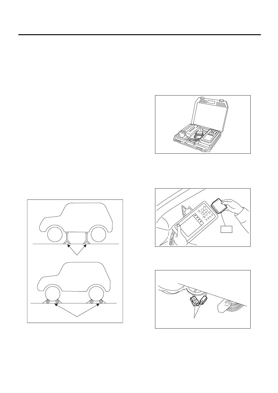
2) Raise the vehicle using a garage jack and place
on safety stands or drive the vehicle onto free roll-
ers.
WARNING:
• Before raising the vehicle, ensure parking
brakes are applied.
• Do not use a pantograph jack in place of a
safety stand.
• Secure a rope or wire to the front and rear
towing or tie-down hooks to prevent the lateral
runout of front wheels.
• Do not abruptly depress/release clutch pedal
or accelerator pedal during works even when
engine is operating at low speeds since this
may cause vehicle to jump off free rollers.
• In order to prevent the vehicle from slipping
due to vibration, do not place any wooden
blocks or similar items between the safety
stands and the vehicle.
• Since the rear wheels will also rotate, do not
place anything near them. Also, make sure that
nobody goes in front of the vehicle.
2. SUBARU SELECT MONITOR
1) After performing diagnostics and clearing the
memory, check for any remaining unresolved trou-
ble data. <Ref. to EN(H4SO)-47, Clear Memory
Mode.>
2) Warm up engine.
3) Prepare Subaru Select Monitor kit. <Ref. to
EN(H4SO)-8, PREPARATION TOOL, General De-
scription.>
4) Connect diagnosis cable to Subaru Select Mon-
itor.
5) Insert cartridge into Subaru Select Monitor.
<Ref. to EN(H4SO)-8, PREPARATION TOOL,
General Description.>
6) Connect test mode connector (A) at the lower
portion of instrument panel (on the driver's side), to
the side of the center console box.
(A) Safety stand
(B) Free rollers
EN-00041
( A )
( B )
EN-00038
ST
EN-00039
EN-00711
( A )
EN(H4SO)-43
ENGINE (DIAGNOSTICS)
INSPECTION MODE
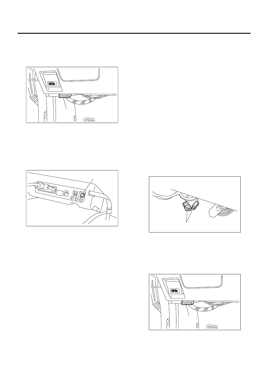
7) Connect Subaru Select Monitor to data link con-
nector.
(1) Connect Subaru Select Monitor to data link
connector (A) located in the lower portion of the
instrument panel (on the driver's side).
(2) Connect diagnosis cable to data link con-
nector.
CAUTION:
Do not connect scan tools except for Subaru
Select Monitor and OBD-II general scan tool.
8) Turn ignition switch to ON (engine OFF) and
Subaru Select Monitor switch to ON.
9) On the «Main Menu» display screen, select the
{2. Each System Check} and press the [YES] key.
10) On the «System Selection Menu» display
screen, select the {Engine Control System} and
press the [YES] key.
11) Press the [YES] key after displayed the infor-
mation of engine type.
12) On the «Engine Diagnosis» display screen, se-
lect the {Dealer Check Mode Procedure} and press
the [YES] key.
13) When the “Perform Inspection (Dealer Check)
Mode?” is shown on the display screen, press the
[YES] key.
14) Perform subsequent procedures as instructed
on the display screen.
• If trouble still remains in the memory, the corre-
sponding diagnostic trouble code (DTC) appears
on the display screen.
NOTE:
• For detailed operation procedure, refer to the
SUBARU SELECT MONITOR OPERATION MAN-
UAL.
• For detailed concerning diagnostic trouble
codes, refer to the List of Diagnostic Trouble Code
(DTC).
<Ref. to EN(H4SO)-83, List of Diagnostic Trouble
Code (DTC).>
• Release the parking brake.
• The speed difference between front and rear
wheels may light either the ABS warning light, but
this indicates no malfunctions. When engine con-
trol diagnosis is finished, perform the ABS memory
clearance procedure of self-diagnosis system.
3. OBD-II GENERAL SCAN TOOL
1) After performing diagnostics and clearing the
memory, check for any remaining unresolved trou-
ble data: <Ref. to EN(H4SO)-47, Clear Memory
Mode.>
2) Warm up engine.
3) Connect test mode connector (A) at the lower
side of the instrument panel (on the driver's side),
to the side of the center console box.
4) Connect the OBD-II general scan tool to its data
link connector (A) in the lower portion of the instru-
ment panel (on the driver's side).
CAUTION:
Do not connect the scan tools except for Suba-
ru Select Monitor and OBD-II general scan tool.
(A) Power switch
EN-00710
( A )
EN-00040
( A )
EN-00711
( A )
EN-00710
( A )
Нет комментариевНе стесняйтесь поделиться с нами вашим ценным мнением.
Текст