Subaru Legacy III (2000-2003 year). Service manual — part 364
EN(H6DO)-258
ENGINE (DIAGNOSTICS)
DIAGNOSTIC PROCEDURE WITH DIAGNOSTIC TROUBLE CODE (DTC)
BJ:DTC P0508 — IDLE CONTROL SYSTEM CIRCUIT LOW —
• DTC DETECTING CONDITION:
• Immediately at fault recognition
• TROUBLE SYMPTOM:
• Erroneous idling
• Engine stalls.
• Engine breathing
CAUTION:
After repair or replacement of faulty parts, conduct Clear Memory Mode <Ref. to EN(H6DO)-54, OP-
ERATION, Clear Memory Mode.> and Inspection Mode <Ref. to EN(H6DO)-47, OPERATION, Inspec-
tion Mode.>.
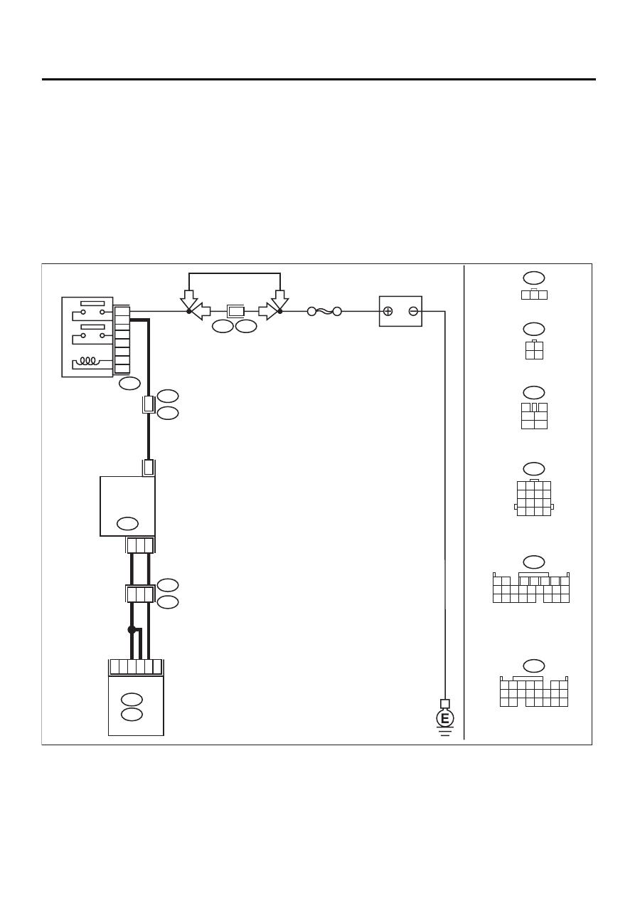
• WIRING DIAGRAM:
EN-01094
C17
C10
A22
B20
E1
ECM
2
3
1
9
3
IDLE
AIR CONTROL
SOLENOID
VALVE
E7
B20
E1
B47
B134
A:
B136
C:
B47
3
4
1
2
5
6
B134
B20
1 2 3 4
5 6 7 8
9 10 11 12
13 14 15 16
E7
B136
SBF-5
BATTERY
MAIN RELAY
1
2
3
5
4
6
4
F46
3 4
1 2
1 2 3
1 2
7
8 9
5
6
3
4
10 11 12
19 20 21
13 14 15 16
17 18
22 23 24
1 2 3 4
10 11 12
19 20 21
13
5
6
14 15
7
8 9
16 17
18
22
2
B108
F46
RHD
LHD
LHD
RHD

EN(H6DO)-259
ENGINE (DIAGNOSTICS)
DIAGNOSTIC PROCEDURE WITH DIAGNOSTIC TROUBLE CODE (DTC)
Step
Value
Yes
No
1
CHECK OUTPUT SIGNAL FROM ECM.
1) Turn ignition switch to ON.
2) Measure voltage between ECM and chas-
sis ground.
Connector & terminal
(B136) No. 10 (+) — Chassis ground (
−−−−
):
Does the measured value exceed the spec-
ified value?
3 V
Repair poor con-
tact in ECM con-
nector.
2
CHECK POWER SUPPLY TO IDLE AIR CON-
TROL SOLENOID VALVE.
1) Turn ignition switch to OFF.
2) Disconnect connector from idle air control
solenoid valve.
3) Turn ignition switch to ON.
4) Measure voltage between idle air control
solenoid valve and engine ground.
Connector & terminal
(E7) No. 2 (+) — Engine ground (
−−−−
):
Does the measured value exceed the spec-
ified value?
10 V
Repair harness
and connector.
NOTE:
In this case, repair
the following:
• Open circuit in
harness between
idle air control
solenoid valve and
main relay con-
nector
• Poor contact in
coupling connector
3
CHECK HARNESS BETWEEN ECM AND
IDLE AIR CONTROL SOLENOID VALVE
CONNECTOR.
1) Turn ignition switch to OFF.
2) Disconnect connector from ECM.
3) Measure resistance of harness between
ECM and idle air control solenoid valve
connector.
Connector & terminal
(B136) No. 10 — (E7) No. 1:
Is the measured value less than the speci-
fied value?
1
Ω
Repair harness
and connector.
NOTE:
In this case, repair
the following:
• Open circuit in
harness between
ECM and idle air
control solenoid
valve connector
• Poor contact in
coupling connector
4
CHECK HARNESS BETWEEN ECM AND
IDLE AIR CONTROL SOLENOID VALVE
CONNECTOR.
Measure resistance of harness between ECM
and chassis ground.
Connector & terminal
(B136) No. 10 — Chassis ground:
Is the measured value less than the specified
value?
10
Ω
Repair ground
short circuit in har-
ness between
ECM and idle air
control solenoid
valve connector.
5
CHECK GROUND CIRCUIT OF IDLE AIR
CONTROL SOLENOID VALVE.
Measure resistance of harness between idle
air control solenoid valve connector and
engine ground.
Connector & terminal
(E7) No. 3 — Engine ground:
Is the measured value less than the specified
value?
5
Ω
Repair open circuit
in harness
between idle air
control solenoid
valve connector
and engine ground
terminal.
6
CHECK POOR CONTACT.
Check poor contact in ECM and idle air control
solenoid valve connectors.
Is there poor contact in ECM and idle air con-
trol solenoid valve connectors?
There is poor contact.
Repair poor con-
tact in ECM and
idle air control
solenoid valve
connectors.
Replace idle air
control solenoid
valve. <Ref. to
FU(H6DO)-36, Idle
Air Control Sole-
noid Valve.>

EN(H6DO)-260
ENGINE (DIAGNOSTICS)
DIAGNOSTIC PROCEDURE WITH DIAGNOSTIC TROUBLE CODE (DTC)
BK:DTC P0509 — IDLE CONTROL SYSTEM CIRCUIT HIGH —
• DTC DETECTING CONDITION:
• Immediately at fault recognition
• TROUBLE SYMPTOM:
• Erroneous idling
• Engine stalls.
• Engine breathing
CAUTION:
After repair or replacement of faulty parts, conduct Clear Memory Mode <Ref. to EN(H6DO)-54, OP-
ERATION, Clear Memory Mode.> and Inspection Mode <Ref. to EN(H6DO)-47, OPERATION, Inspec-
tion Mode.>.
• WIRING DIAGRAM:
EN-01094
C17
C10
A22
B20
E1
ECM
2
3
1
9
3
IDLE
AIR CONTROL
SOLENOID
VALVE
E7
B20
E1
B47
B134
A:
B136
C:
B47
3
4
1
2
5
6
B134
B20
1 2 3 4
5 6 7 8
9 10 11 12
13 14 15 16
E7
B136
SBF-5
BATTERY
MAIN RELAY
1
2
3
5
4
6
4
F46
3 4
1 2
1 2 3
1 2
7
8 9
5
6
3
4
10 11 12
19 20 21
13 14 15 16
17 18
22 23 24
1 2 3 4
10 11 12
19 20 21
13
5
6
14 15
7
8 9
16 17
18
22
2
B108
F46
RHD
LHD
LHD
RHD

EN(H6DO)-261
ENGINE (DIAGNOSTICS)
DIAGNOSTIC PROCEDURE WITH DIAGNOSTIC TROUBLE CODE (DTC)
Step
Value
Yes
No
1
CHECK THROTTLE CABLE.
Does throttle cable have play for adjustment?
Throttle cable has play for
adjustment.
Adjust throttle
cable. <Ref. to
SP(H6DO)-8,
Accelerator Con-
trol Cable.>
2
CHECK OUTPUT SIGNAL FROM ECM.
1) Turn ignition switch to ON.
2) Measure voltage between ECM and chas-
sis ground.
Connector & terminal
(B136) No. 10 (+) — Chassis ground (
−−−−
):
Does the measured value exceed the spec-
ified value?
10 V
3
CHECK OUTPUT SIGNAL FROM ECM.
1) Turn ignition switch to OFF.
2) Disconnect connector from idle air control
solenoid valve.
3) Turn ignition switch to ON.
4) Measure voltage between ECM and chas-
sis ground.
Connector & terminal
(B136) No. 10 (+) — Chassis ground (
−−−−
):
Does the measured value exceed the spec-
ified value?
10 V
Repair battery
short circuit in har-
ness between
ECM and idle air
control solenoid
valve connector.
After repair,
replace ECM.
<Ref. to
FU(H6DO)-46,
Engine Control
Module.>
Replace idle air
control solenoid
valve <Ref. to
FU(H6DO)-36, Idle
Air Control Sole-
noid Valve.> and
ECM <Ref. to
FU(H6DO)-46,
Engine Control
Module.>.
4
CHECK OUTPUT SIGNAL FROM ECM.
Measure voltage between ECM and chassis
ground.
Connector & terminal
(B136) No. 10 (+) — Chassis ground (
−−−−
):
Does the voltage change exceed the specified
value by shaking harness and connector of
ECM while monitoring the value with voltage
meter?
10 V
Repair battery
short circuit in har-
ness between
ECM and idle air
control solenoid
valve connector.
After repair,
replace ECM.
<Ref. to
FU(H6DO)-46,
Engine Control
Module.>
Contact SUBARU
distributor service.
NOTE:
Inspection by DTM
is required, be-
cause probable
cause is deteriora-
tion of multiple
parts.
Нет комментариевНе стесняйтесь поделиться с нами вашим ценным мнением.
Текст