Subaru Legacy III (2000-2003 year). Service manual — part 581
AT-58
AUTOMATIC TRANSMISSION (DIAGNOSTICS)
DIAGNOSTIC PROCEDURE WITH DIAGNOSTIC TROUBLE CODE (DTC)
E: DTC 33 FRONT VEHICLE SPEED SENSOR
DIAGNOSIS:
• The vehicle speed signal is abnormal.
• The circuit in combination meter is faulty.
• The harness connector between TCM and vehicle speed sensor is in short or open.
TROUBLE SYMPTOM:
• Erroneous idling.
• Engine stalls.
• Poor driving performance.
AT-59
AUTOMATIC TRANSMISSION (DIAGNOSTICS)
DIAGNOSTIC PROCEDURE WITH DIAGNOSTIC TROUBLE CODE (DTC)
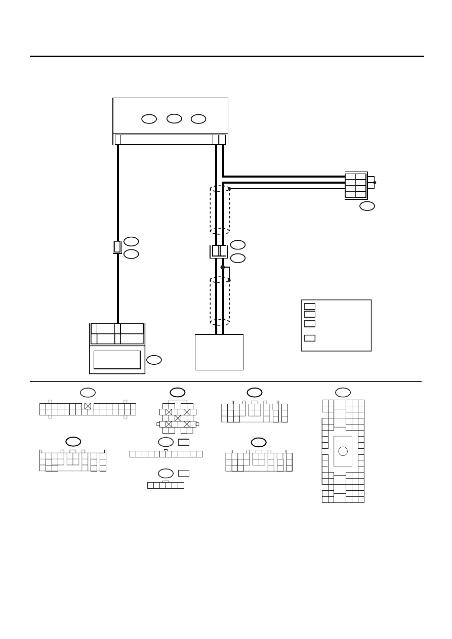
WIRING DIAGRAM:
AT-00779
i10
B36
i1
17
18
B18
C17
E4
H6
H4
11
13
A10
B11
B53
T4
TCM
B54
A:
B55
B:
B56
C:
NT
TB
4
5
6
SHIELD AND
SENSOR GROUND
JOINT CONNECTOR
COMBINATION
METER
SPEEDOMETER
FRONT
VEHICLE SPEED
SENSOR
B54
B56
B55
B11
1 2
5
6 7
8
13
14 15
16
9 10
11 12
3 4
17 18
19 20
1 2 3 4
10 11 12
19 20 21
13
5 6
14 15
7
8
9
16
17
18
22
23
24
1 2 3 4
10 11 12
19 20 21
13
5 6
14 15
7
8
9
16
17
18
22
23
24
1 2 3 4
10 11 12
19 20 21
13
5 6
14 15
7
8
9
16
17
18
22
23
24
i10
1 2 3 4 5 6 7
8 9 10 11 12 13 14
15 16 17 18 19 20 21 22 23 24 25 26 27 28 29 30
1 2 3 4 5 6 7 8 9 10 11 12
B53
B36
B4 B5 B6
A4 A5 A6
C5 C6
F6
D4 D5 D6
F1
H1
C4
G6
G1
C2
K1
M1 M2
K6
L1
D1 D2
A1 A2
B1 B2
I6
J6
L2
I1
J1
H6
M4 M5 M6
L4 L5 L6
N5 N6
O4 O5 O6
N4
P4 P5
N2
O1 O2
P1 P2
N3
O3
P3
P6
A3
B3
C3
E4 E5 E6
E1 E2
: EXCEPT 3.0L MODEL
AND TURBO MODEL
: 3.0L MODEL
AND TURBO MODEL
H4
H6
B53
1 2 3 4 5 6
: NON-TURBO MODEL
NT
: TURBO MODEL
TB
: NT
: TB
1
2
3

AT-60
AUTOMATIC TRANSMISSION (DIAGNOSTICS)
DIAGNOSTIC PROCEDURE WITH DIAGNOSTIC TROUBLE CODE (DTC)
Step
Value
Yes
No
1
CHECK HARNESS CONNECTOR BETWEEN
TCM AND TRANSMISSION.
1) Turn ignition switch to OFF.
2) Disconnect connector from TCM and trans-
mission.
3) Measure resistance of harness between
TCM and transmission connector.
Connector & terminal
(B55) No. 18 — (B11) No. 17:
Is the measured value less than the speci-
fied value?
1
Ω
Repair open circuit
in harness
between TCM and
transmission con-
nector.
2
CHECK HARNESS CONNECTOR BETWEEN
TCM AND TRANSMISSION.
Measure resistance of harness between TCM
and transmission connector.
Connector & terminal
(B54) No. 10 — (B11) No. 18:
Is the measured value less than the specified
value?
1
Ω
Repair open circuit
in harness
between TCM and
transmission con-
nector, and poor
contact in cou-
pling connector.
3
CHECK HARNESS CONNECTOR BETWEEN
TCM AND TRANSMISSION.
Measure resistance of harness between TCM
and transmission connector.
Connector & terminal
(B54) No. 10 — Chassis ground:
Does the measured value exceed the specified
value?
1 M
Ω
Repair short circuit
in harness
between TCM and
transmission con-
nector.
4
CHECK HARNESS CONNECTOR BETWEEN
TCM AND TRANSMISSION.
Measure resistance of harness between TCM
and transmission connector.
Connector & terminal
(B55) No. 18 — Chassis ground:
Does the measured value exceed the specified
value?
1 M
Ω
Repair short circuit
in harness
between TCM and
transmission con-
nector, and poor
contact in cou-
pling connector.
5
CHECK FRONT VEHICLE SPEED SENSOR.
Measure resistance between transmission
connector receptacle's terminals.
Connector & terminal
(T4) No. 17 — No. 18:
Is the measured value within the specified
range?
450 — 650
Ω
Replace front vehi-
cle speed sensor.
<Ref. to AT-54,
Front Vehicle
Speed Sensor.>
6
PREPARE OSCILLOSCOPE.
Do you have oscilloscope?
Oscilloscope is available.
7
PREPARE SUBARU SELECT MONITOR.
Do you have a Subaru Select Monitor?
Subaru Select Monitor is avail-
able.

AT-61
AUTOMATIC TRANSMISSION (DIAGNOSTICS)
DIAGNOSTIC PROCEDURE WITH DIAGNOSTIC TROUBLE CODE (DTC)
8
CHECK INPUT SIGNAL FOR TCM.
1) Connect all connectors.
2) Lift-up or raise the vehicle and place safety
stands.
NOTE:
Raise all wheels off floor.
3) Start the engine and set vehicle in 20 km/h
(12 MPH) condition.
NOTE:
The speed difference between front and rear
wheels may light the ABS warning light, but this
indicates no malfunction. When AT control di-
agnosis is finished, perform the ABS memory
clearance procedure of on-board diagnostics
system. <Ref. to ABS-22, Clear Memory
Mode.> or <Ref. to VDC-25, Clear Memory
Mode.>
4) Measure voltage between TCM connector
terminals.
Connector & terminal
(B55) No. 18 (+) — (B54) No. 10 (
−−−−
):
Does the measured value exceed the spec-
ified value?
AC 1 V
Even if “POWER”
indicator lights up,
the circuit has
returned to a nor-
mal condition at
this time. A tempo-
rary poor connec-
tor or harness may
be the case.
Repair harness or
connector in the
front vehicle speed
sensor circuit.
9
CHECK FRONT VEHICLE SPEED SENSOR
USING OSCILLOSCOPE.
1) Connect all connectors.
2) Lift-up the vehicle and place safety stand.
NOTE:
Raise all wheels off ground.
3) Set oscilloscope to TCM connector termi-
nals.
Connector & terminal
Positive probe; (B55) No. 18
Ground; (B54) No. 10
4) Start the engine, and drive the wheels
slowly.
NOTE:
The speed difference between front and rear
wheels may light the ABS warning light, but this
indicates no malfunctions. When AT control di-
agnosis is finished, perform the ABS memory
clearance procedure of self-diagnosis system.
<Ref. to ABS-22, Clear Memory Mode.> or
<Ref. to VDC-25, Clear Memory Mode.>
5) Measure signal voltage indicated on oscillo-
scope.
Does the measured value exceed the spec-
ified value?
AC 1 V
Even if “POWER”
indicator lights up,
the circuit has
returned to a nor-
mal condition at
this time. A tempo-
rary poor connec-
tor or harness may
be the case.
Repair harness or
connector in the
front vehicle speed
sensor circuit.
Step
Value
Yes
No
Нет комментариевНе стесняйтесь поделиться с нами вашим ценным мнением.
Текст