Subaru Legacy III (2000-2003 year). Service manual — part 475
EN(H4DOSTC)-70
ENGINE (DIAGNOSTICS)
DIAGNOSTIC PROCEDURE WITH DIAGNOSTIC TROUBLE CODE (DTC)
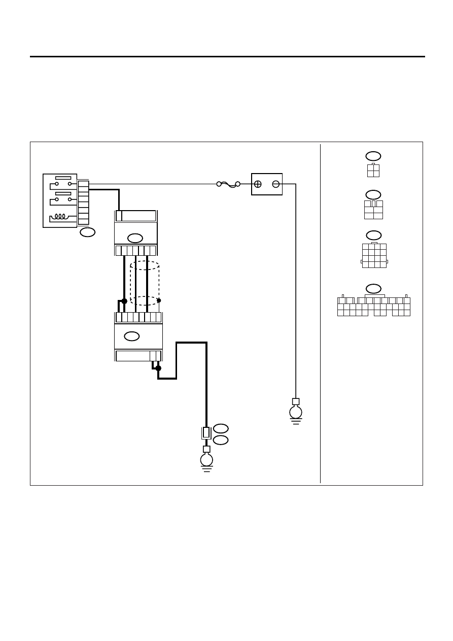
B: DTC P0032 — HO2S HEATER CONTROL CIRCUIT HIGH (BANK 1 SENSOR
1) —
CAUTION:
After repair or replacement of faulty parts, conduct Clear Memory Mode <Ref. to EN(H4DOSTC)-35,
OPERATION, Clear Memory Mode.> and Inspection Mode <Ref. to EN(H4DOSTC)-33, Inspection
Mode.> .
• WIRING DIAGRAM:
EN-00933
BATTERY
MAIN RELAY
SBF-5
B47
1
2
3
5
4
6
E
E
E3
3
8
9
4
5
19
29
18
ECM
B137
B22
2
4
1
3
B18
FRONT OXYGEN
(A/F) SENSOR
3 4
1 2
3
4
1
2
5
6
1 2 3 4
5 6 7 8
9 10 11 12
13 14 15 16
B22
B47
B18
B137
1
2
7
8
9
5
6
3
4
10 11 12
19 20 21
29 30 31
13 14 15 16 17
27 28
18
22 23 24 25 26

EN(H4DOSTC)-71
ENGINE (DIAGNOSTICS)
DIAGNOSTIC PROCEDURE WITH DIAGNOSTIC TROUBLE CODE (DTC)
Step
Value
Yes
No
1
CHECK OUTPUT SIGNAL FROM ECM.
1) Turn the ignition switch to ON.
2) Measure the voltage between ECM con-
nector and chassis ground.
Connector & terminal
(B137) No. 4 (+) — Chassis ground (
−−−−
):
(B137) No. 5 (+) — Chassis ground (
−−−−
):
Does the measured value exceed the spec-
ified value?
8 V
2
CHECK FRONT OXYGEN (A/F) SENSOR
HEATER CURRENT.
1) Turn the ignition switch to OFF.
2) Repair the battery short circuit in harness
between ECM and front oxygen (A/F) sen-
sor connector.
3) Turn the ignition switch to ON.
4) Read the data of front oxygen (A/F) sensor
heater current using Subaru Select Monitor.
Does the measured value exceed the spec-
ified value?
NOTE:
For detailed operation procedure, refer to the
“READ CURRENT DATA FOR ENGINE”. <Ref.
to EN(H4DOSTC)-26, Subaru Select Monitor.>
2.3 A
Replace the ECM.
<Ref. to
FU(H4DOSTC)-
40, Engine Con-
trol Module.>
END
3
CHECK OUTPUT SIGNAL FROM ECM.
Measure the voltage between ECM connector
and chassis ground.
Connector & terminal
(B137) No. 4 (+) — Chassis ground (
−−−−
):
(B137) No. 5 (+) — Chassis ground (
−−−−
):
Does the measured value exceed the specified
value by shaking harness and connector of
ECM while monitoring the value with voltage
meter?
8.0 V
Repair the battery
short circuit in har-
ness between
ECM and front
oxygen (A/F) sen-
sor connector.
END
EN(H4DOSTC)-72
ENGINE (DIAGNOSTICS)
DIAGNOSTIC PROCEDURE WITH DIAGNOSTIC TROUBLE CODE (DTC)
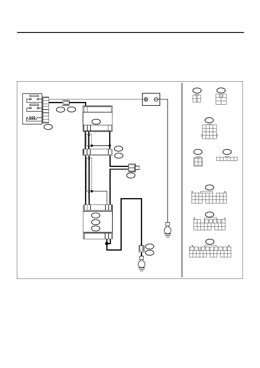
C: DTC P0037 — HO2S HEATER CONTROL CIRCUIT LOW (BANK 1 SENSOR 2)
—
CAUTION:
After repair or replacement of faulty parts, conduct Clear Memory Mode <Ref. to EN(H4DOSTC)-35,
OPERATION, Clear Memory Mode.> and Inspection Mode <Ref. to EN(H4DOSTC)-33, Inspection
Mode.> .
• WIRING DIAGRAM:
EN-00934
BATTERY
MAIN RELAY
B47
1
2
3
5
4
6
E
E
E3
3
3
6
B22
B122
3
4
1
2
5
6
1 2 3 4
5 6 7 8
9 10 11 12
13 14 15 16
B22
B135
B136
B122
B47
T5
B137
1
2
7
8
9
5
6
3
4
10 11 12
19 20 21
29 30 31
13 14 15 16 17
27 28
18
22 23 24 25 26
1
4
2
3
T6
REAR
OXYGEN SENSOR
D8
D9
C13
B17
B26
B19
ECM
B136
B137
C :
B135
B :
D :
1 2 3 4 5 6
5 6
7 8
2
1
9
4
3
10
24
22
23
25
11 12 13 14 15
26 27 28
16 17 18 19
20 21
1 2
7
8 9
5
6
3
4
10 11 12
19 20 21
13 14 15 16
17 18
22 23 24
1
2
3
4
2
4
3
1
T5
B19
T5
B19
T6
2 1
4 3

EN(H4DOSTC)-73
ENGINE (DIAGNOSTICS)
DIAGNOSTIC PROCEDURE WITH DIAGNOSTIC TROUBLE CODE (DTC)
Step
Value
Yes
No
1
CHECK GROUND CIRCUIT OF ECM.
1) Turn the ignition switch to OFF.
2) Disconnect the connector from ECM.
3) Measure the resistance of harness
between ECM connector and chassis
ground.
Connector & terminal
(B137) No. 8 — Chassis ground:
(B137) No. 9 — Chassis ground:
Is the measured value less than the speci-
fied value?
5
Ω
2
CHECK CURRENT DATA.
1) Start the engine.
2) Read the data of rear oxygen sensor heater
current using Subaru Select Monitor.
Does the measured value exceed the spec-
ified value?
NOTE:
For detailed operation procedure, refer to the
“READ CURRENT DATA FOR ENGINE”. <Ref.
to EN(H4DOSTC)-26, Subaru Select Monitor.>
0.2 A
Repair the con-
nector.
NOTE:
In this case, repair
the following:
• Poor contact in
rear oxygen sen-
sor connector
• Poor contact in
rear oxygen sen-
sor connecting
harness connector
• Poor contact in
ECM connector
3
CHECK OUTPUT SIGNAL FROM ECM.
1) Start and idle the engine.
2) Measure the voltage between ECM con-
nector and chassis ground.
Connector & terminal
(B136) No. 13 (+) — Chassis ground (
−−−−
):
Is the measured value less than the speci-
fied value?
1.0 V
4
CHECK OUTPUT SIGNAL FROM ECM.
Measure the voltage between ECM connector
and chassis ground.
Connector & terminal
(B136) No. 13 (+) — Chassis ground (
−−−−
):
Is the measured value less than the specified
value by shaking harness and connector of
ECM while monitoring the value with voltage
meter?
1.0 V
Repair the poor
contact in ECM
connector.
5
CHECK OUTPUT SIGNAL FROM ECM.
1) Disconnect the connector from rear oxygen
sensor.
2) Measure the voltage between ECM con-
nector and chassis ground.
Connector & terminal
(B136) No. 13 (+) — Chassis ground (
−−−−
):
Is the measured value less than the speci-
fied value?
1.0 V
Replace the ECM.
<Ref. to
FU(H4DOSTC)-
40, Engine Con-
trol Module.>
Repair the battery
short circuit in har-
ness between
ECM and rear oxy-
gen sensor con-
nector. After
repair, replace the
ECM. <Ref. to
FU(H4DOSTC)-
40, Engine Con-
trol Module.>
Нет комментариевНе стесняйтесь поделиться с нами вашим ценным мнением.
Текст