Subaru Legacy III (2000-2003 year). Service manual — part 103
EN(H4SO)-24
ENGINE (DIAGNOSTICS)
ENGINE CONTROL MODULE (ECM) I/O SIGNAL
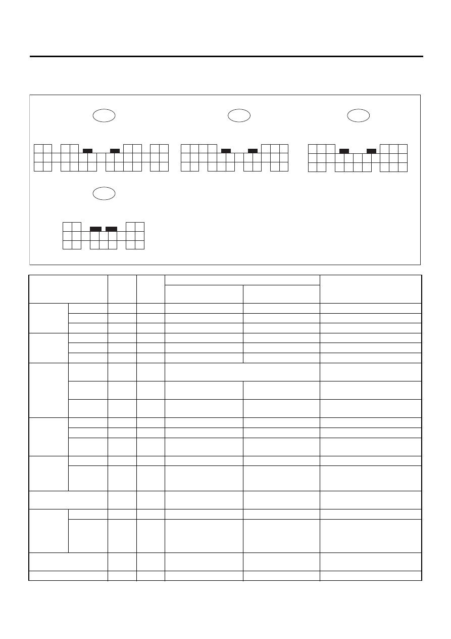
5. Engine Control Module (ECM) I/O Signal
A: ELECTRICAL SPECIFICATION
Content
Con-
nector
No.
Termi-
nal No.
Signal (V)
Note
Ignition SW ON
(Engine OFF)
Engine ON (Idling)
Crank-
shaft posi-
tion sensor
Signal (+)
B135
6
0
−
7 — +7
Sensor output waveform
Signal (
−
)
B135
17
0
0
—
Shield
B135
28
0
0
—
Camshaft
position
sensor
Signal (+)
B135
7
0
−
7 — +7
Sensor output waveform
Signal (
−
)
B135
18
0
0
—
Shield
B135
28
0
0
—
Throttle
position
sensor
Signal
B135
13
Fully closed: 0.2 — 1.0
Fully opened: 4.2 — 4.7
—
Power
supply
B135
3
5
5
—
GND (sen-
sor)
B135
19
0
0
—
Rear oxy-
gen sen-
sor
Signal
B135
14
0
0 — 0.9
—
Shield
B137
15
0
0
—
GND (sen-
sor)
B135
19
0
0
—
Front oxy-
gen (A/F)
sensor
heater
Signal 1
B136
6
0 — 1.0
0 — 1.0
—
Signal 2
B136
17
0 — 1.0
0 — 1.0
—
Rear oxygen sensor
heater signal
B136
4
0 — 1.0
0 — 1.0
—
Engine
coolant
tempera-
ture sen-
sor
Signal
B135
12
1.0 — 1.4
1.0 — 1.4
After warm-up the engine.
GND (sen-
sor)
B135
19
0
0
After warm-up the engine.
Vehicle speed signal
B137
10
0 or 5
0 or 5
“5” and “0” are repeatedly dis-
played when vehicle is driven.
Starter switch
B136
20
0
0
Cranking: 8 — 14
EN-00709
B134
8 7
6 5
4
4
5
6
7
3
3
2 1
2 1
9
to
B135
to
B136
to
23 22 21 20 19 18 17 16 15 14 13 12 11 10
9 8
19 18 17 16 15 14 13 12 11 10
35 34
33 32 31 30
29 28 27 26
25 24
B137
to
28 27
26 25 24
23 22
21 20
4
5
6
7
3 2 1
9 8
19
20
18
17 16 15 14 13 12 11 10
26 25
24 23
21
22
4
5
6
3
2 1
19
20
18 17 16
15 14
7
9 8
13 12 11 10

EN(H4SO)-25
ENGINE (DIAGNOSTICS)
ENGINE CONTROL MODULE (ECM) I/O SIGNAL
A/C switch
B136
11
ON: 10 — 13
OFF: 0
ON: 13 — 14
OFF: 0
—
Ignition switch
B136
10
10 — 13
13 — 14
—
Neutral position switch
(MT)
B136
21
ON: 5
OFF: 0
Switch is ON when gear is in
neutral position.
Neutral position switch
(AT)
B136
21
ON: 0
OFF: 5
Switch is ON when shift is in “N”
or “P” position.
Test mode connector
B136
3
5
5
When connected: 0
Knock
sensor
Signal
B135
16
2.8
2.8
—
Shield
B135
27
0
0
—
Back-up power supply
B135
9
10 — 13
13 — 14
Ignition switch “OFF”: 10 — 13
Control unit power sup-
ply
B135
1
10 — 13
13 — 14
—
B135
2
10 — 13
13 — 14
—
Sensor power supply
B135
3
5
5
—
Ignition
control
#1, #2
B134
33
0
1 — 3.4
Waveform
#3, #4
B134
32
0
1 — 3.4
Waveform
Fuel injec-
tor
#1
B134
34
10 — 13
1 — 14
Waveform
#2
B134
23
10 — 13
1 — 14
Waveform
#3
B134
22
10 — 13
1 — 14
Waveform
#4
B134
8
10 — 13
1 — 14
Waveform
Idle air
control
solenoid
valve
Signal 1
B134
20
—
1 — 13
Waveform
Signal 2
B134
6
—
1 — 13
Waveform
Signal 3
B134
5
—
1 — 13
Waveform
Signal 4
B134
19
—
1 — 13
Waveform
Fuel pump relay control
B134
2
ON: 0.5, or less
OFF: 10 — 13
0.5, or less
—
A/C relay control
B134
9
ON: 0.5, or less
OFF: 10 — 13
ON: 0.5, or less
OFF: 13 — 14
—
Radiator fan relay 1
control
B134
14
ON: 0.5, or less
OFF: 10 — 13
ON: 0.5, or less
OFF: 13 — 14
—
Radiator fan relay 2
control
B134
13
ON: 0.5, or less
OFF: 10 — 13
ON: 0.5, or less
OFF: 13 — 14
With A/C vehicles only
Self-shutoff control
B136
12
10 — 13
13 — 14
—
Malfunction indicator
lamp
B134
28
—
—
Light “ON”: 1, or less
Light “OFF”: 10 — 14
Engine speed output
B134
10
—
0 — 13, or more
Waveform
Torque control 1 signal
B136
1
5
5
—
Torque control 2 signal
B136
18
5
5
—
Torque control cut sig-
nal
B136
5
8
8
—
Purge control solenoid
valve
B134
29
ON: 1, or less
OFF: 10 — 13
ON: 1, or less
OFF: 13 — 14
—
Fuel level sensor
B135
25
0.12 — 4.75
0.12 — 4.75
—
EGR sole-
noid valve
Signal 1
B134
18
0 or 10 — 13
0 or 10 — 13
—
Signal 2
B134
17
0 or 10 — 13
0 or 10 — 13
—
Signal 3
B134
16
0 or 10 — 13
0 or 10 — 13
—
Signal 4
B134
15
0 or 10 — 13
0 or 10 — 13
—
AT diagnosis input sig-
nal
B137
19
Less than 1
←→
More
than 4
Less than 1
←→
More
than 4
Waveform
Small light switch
B137
20
ON: 0
OFF: 10 — 13
ON: 0
OFF: 13 — 14
—
Content
Con-
nector
No.
Termi-
nal No.
Signal (V)
Note
Ignition SW ON
(Engine OFF)
Engine ON (Idling)

EN(H4SO)-26
ENGINE (DIAGNOSTICS)
ENGINE CONTROL MODULE (ECM) I/O SIGNAL
Blower fan switch
B137
13
ON: 0
OFF: 10 — 13
ON: 0
OFF: 13 — 14
—
Rear defogger switch
B137
4
ON: 0
OFF: 10 — 13
ON: 0
OFF: 13 — 14
—
Front oxygen (A/F) sen-
sor signal 1
B136
13
—
2.05 — 2.25
—
Front oxygen (A/F) sen-
sor signal 2
B136
22
—
1.75 — 1.95
—
Pressure sensor
B135
15
4.0 — 4.8
1.1 — 1.9
—
Intake air temperature
sensor
B137
6
3.15 — 3.33
3.15 — 3.33
Intake air temperature: 25
°
C
(75
°
F)
Immobilizer input/out-
put 1
B137
17
Less than 1
←→
More
than 4
Less than 1
←→
More
than 4
—
Immobilizer input/out-
put 2
B137
18
Less than 1
←→
More
than 4
Less than 1
←→
More
than 4
—
SSM/GST communica-
tion line
B137
16
Less than 1
←→
More
than 4
Less than 1
←→
More
than 4
—
GND (sensors)
B135
19
0
0
—
GND (injectors)
B134
35
0
0
—
GND (ignition system)
B136
26
0
0
—
GND (power supply)
B134
7
0
0
—
GND (control systems)
B137
14
0
0
—
B135
21
0
0
—
GND (oxygen sensor
heater 1)
B136
5
0
0
—
GND (oxygen sensor
heater 2)
B136
16
0
0
—
Content
Con-
nector
No.
Termi-
nal No.
Signal (V)
Note
Ignition SW ON
(Engine OFF)
Engine ON (Idling)

EN(H4SO)-27
ENGINE (DIAGNOSTICS)
ENGINE CONDITION DATA
6. Engine Condition Data
A: ELECTRICAL SPECIFICATION
Measuring condition:
• After warm-up the engine.
• Gear position is in “N” or “P” position.
• A/C is turned OFF.
• All accessory switches are turned OFF.
Content
Specified data
Engine load
1.6 — 2.9 (%): Idling
6.4 — 12.8 (%): 2,500 rpm racing
Нет комментариевНе стесняйтесь поделиться с нами вашим ценным мнением.
Текст