Subaru Legacy III (2000-2003 year). Service manual — part 493
EN(H4DOSTC)-142
ENGINE (DIAGNOSTICS)
DIAGNOSTIC PROCEDURE WITH DIAGNOSTIC TROUBLE CODE (DTC)
AC:DTC P0340 — CAMSHAFT POSITION SENSOR “A” CIRCUIT (BANK 1 OR
SINGLE SENSOR)N —
• TROUBLE SYMPTOM:
• Engine stalls.
• Failure of engine to start
CAUTION:
After repair or replacement of faulty parts, conduct Clear Memory Mode <Ref. to EN(H4DOSTC)-35,
OPERATION, Clear Memory Mode.> and Inspection Mode <Ref. to EN(H4DOSTC)-33, Inspection
Mode.> .
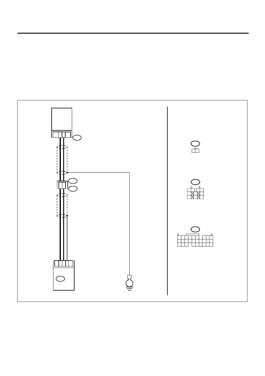
• WIRING DIAGRAM:
EN-00943
4
3
E1
E15
B20
CAMSHAFT
POSITION
SENSOR
2
1
B135 ECM
10
21
1
E
E15
1 2
1 2
3 4
5
6
7
8
9
10
B20
B135
5 6
7 8
2
1
9
4
3
10
24
22
23
25
11 12 13 14 15
26 27 28
16 17 18 19
20 21

EN(H4DOSTC)-143
ENGINE (DIAGNOSTICS)
DIAGNOSTIC PROCEDURE WITH DIAGNOSTIC TROUBLE CODE (DTC)
Step
Value
Yes
No
1
CHECK HARNESS BETWEEN CAMSHAFT
POSITION SENSOR AND ECM CONNEC-
TOR.
1) Turn the ignition switch to OFF.
2) Disconnect the connector from camshaft
position sensor.
3) Measure the resistance of harness
between camshaft position sensor connec-
tor and engine ground.
Connector & terminal
(E15) No. 1 — Engine ground:
Does the measured value exceed the spec-
ified value?
100 k
Ω
Repair the har-
ness and connec-
tor.
NOTE:
In this case, repair
the following:
• Open circuit in
harness between
camshaft position
sensor and ECM
connector
• Poor contact in
ECM connector
• Poor contact in
coupling connector
2
CHECK HARNESS BETWEEN CAMSHAFT
POSITION SENSOR AND ECM CONNEC-
TOR.
Measure the resistance of harness between
camshaft position sensor connector and
engine ground.
Connector & terminal
(E15) No. 1 — Engine ground:
Is the measured value less than the specified
value?
10
Ω
Repair the ground
short circuit in har-
ness between
camshaft position
sensor and ECM
connector.
NOTE:
The harness be-
tween both con-
nectors are
shielded. Repair
ground short circuit
in harness togeth-
er with shield.
3
CHECK HARNESS BETWEEN CAMSHAFT
POSITION SENSOR AND ECM CONNEC-
TOR.
Measure the resistance of harness between
camshaft position sensor connector and
engine ground.
Connector & terminal
(E15) No. 2 — Engine ground:
Is the measured value less than the specified
value?
5
Ω
Repair the har-
ness and connec-
tor.
NOTE:
In this case, repair
the following:
• Open circuit in
harness between
camshaft position
sensor and ECM
connector
• Poor contact in
ECM connector
• Poor contact in
coupling connector
4
CHECK CONDITION OF CAMSHAFT POSI-
TION SENSOR.
Is the camshaft position sensor installation bolt
tightened securely?
Tightened securely.
Tighten the cam-
shaft position sen-
sor installation bolt
securely.
5
CHECK CAMSHAFT POSITION SENSOR.
1) Remove the camshaft position sensor.
2) Measure the resistance between connector
terminals of camshaft position sensor.
Terminals
No. 1 — No. 2:
Is the measured value within the specified
value?
1 — 4 k
Ω
Repair the poor
contact in cam-
shaft position sen-
sor connector.
Replace the cam-
shaft position sen-
sor. <Ref. to
FU(H4DOSTC)-
30, Camshaft
Position Sensor.>
EN(H4DOSTC)-144
ENGINE (DIAGNOSTICS)
DIAGNOSTIC PROCEDURE WITH DIAGNOSTIC TROUBLE CODE (DTC)
AD:DTC P0350 — IGNITION COIL PRIMARY/SECONDARY CIRCUIT —
• TROUBLE SYMPTOM:
• Failure of engine to start
• Erroneous idling
CAUTION:
After repair or replacement of faulty parts, conduct CLEAR MEMORY MODE <Ref. to EN(H4DOSTC)-
35, Clear Memory Mode.> and INSPECTION MODE <Ref. to EN(H4DOSTC)-33, Inspection Mode.> .
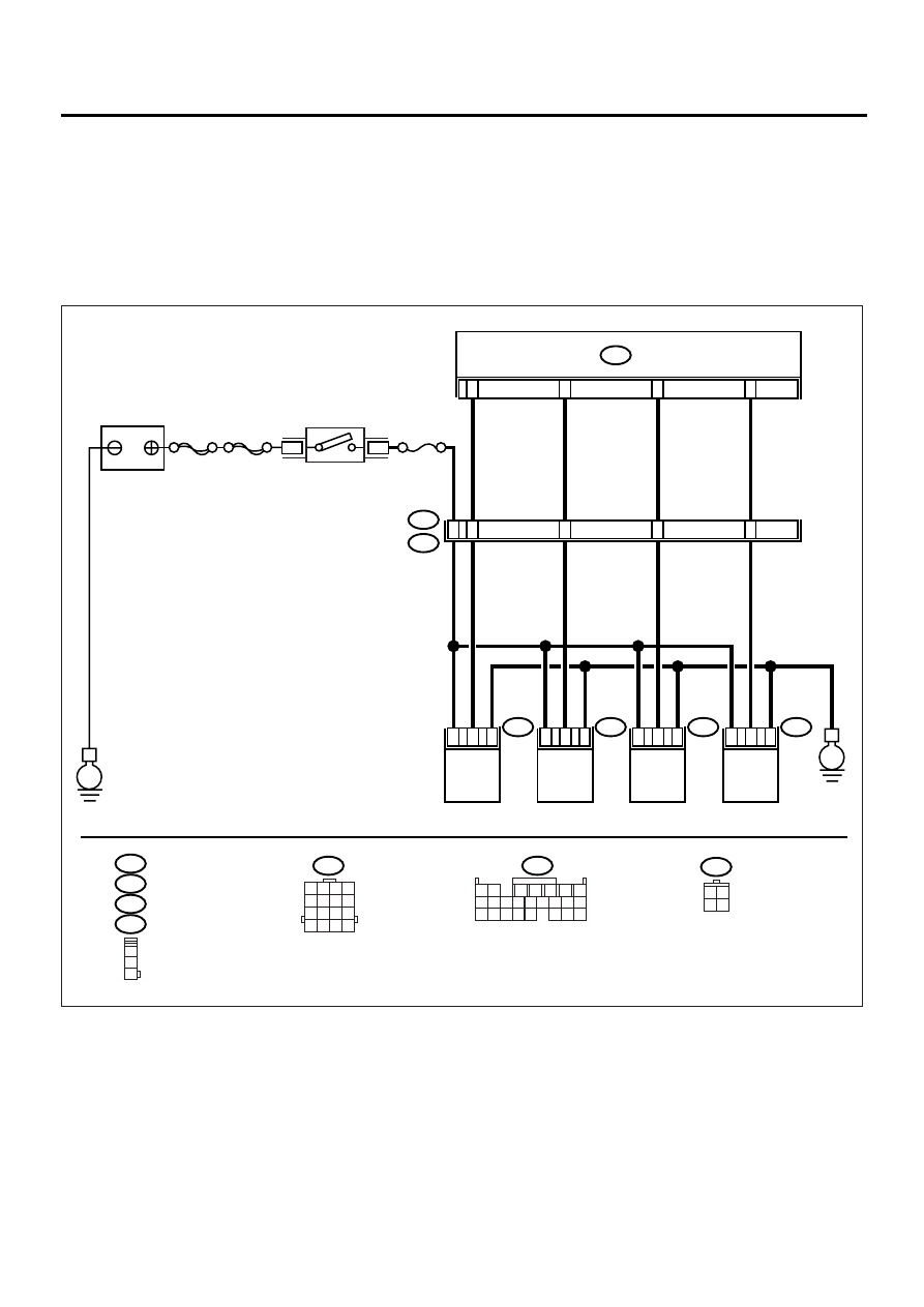
• WIRING DIAGRAM:
EN-00944
SBF-4
SBF-1
B136
24
23
22
21
ECM
No.11
E
E
4
1
E31
E31
E32
E33
E34
IGNITION COIL
No.1
IGNITION COIL
No.2
IGNITION COIL
No.3
IGNITION COIL
No.4
E32
E33
E34
1
2
3
1 2 3 4
5 6 7 8
9 10 11 12
13 14 15 16
B22
B136
1 2
7
8 9
5
6
3
4
10 11 12
19 20 21
13 14 15 16
17 18
22 23 24
B72
3 4
1 2
5
4
6
7
8
3
1
2
3
1
2
3
1
2
3
1
2
B22
E3

EN(H4DOSTC)-145
ENGINE (DIAGNOSTICS)
DIAGNOSTIC PROCEDURE WITH DIAGNOSTIC TROUBLE CODE (DTC)
Step
Value
Yes
No
1
CHECK SPARK PLUG CONDITION.
1) Remove the spark plug. <Ref. to
IG(H4DOSTC)-5, REMOVAL, Spark Plug.>
2) Check the spark plug condition. <Ref. to
IG(H4DOSTC)-6, INSPECTION, Spark
Plug.>
Is spark plug’s status OK?
OK
Replace the spark
plug.
2
CHECK IGNITION SYSTEM FOR SPARKS.
1) Connect the spark plug to ignition coil.
2) Release the fuel pressure. <Ref. to
FU(H4DOSTC)-44, RELEASING OF FUEL
PRESSURE, OPERATION, Fuel.>
3) Contact the spark plug's thread portion on
engine.
4) While opening throttle valve fully, crank the
engine to check that spark occurs at each
cylinder.
Does the spark occur at each cylinder?
Spark occurs.
Check the fuel
pump system.
<Ref. to
EN(H4DOSTC)-
60, FUEL PUMP
CIRCUIT, Diag-
nostics for Engine
Starting Failure.>
3
CHECK POWER SUPPLY CIRCUIT FOR IG-
NITION COIL & IGNITOR ASSEMBLY.
1) Turn the ignition switch to OFF.
2) Disconnect the connector from ignition coil
& ignitor assembly.
3) Turn the ignition switch to ON.
4) Measure the power supply voltage between
ignition coil & ignitor assembly connector
and engine ground.
Connector & terminal
(E31) No. 3 (+) — Engine ground (
−−−−
):
(E32) No. 3 (+) — Engine ground (
−−−−
):
(E33) No. 3 (+) — Engine ground (
−−−−
):
(E34) No. 3 (+) — Engine ground (
−−−−
):
Does the measured value exceed the spec-
ified value?
10 V
Repair the har-
ness and connec-
tor.
NOTE:
In this case, repair
the following:
• Open circuit in
harness between
ignition coil & igni-
tor assembly, and
ignition switch
connector
• Poor contact in
coupling connec-
tors
4
CHECK HARNESS OF IGNITION COIL & IG-
NITOR ASSEMBLY GROUND CIRCUIT.
1) Turn the ignition switch to OFF.
2) Measure the resistance between ignition
coil & ignitor assembly connector and
engine ground.
Connector & terminal
(E31) No. 2 — Engine ground:
(E32) No. 2 — Engine ground:
(E33) No. 2 — Engine ground:
(E34) No. 2 — Engine ground:
Is the measured value less than the speci-
fied value?
5
Ω
Repair the har-
ness and connec-
tor.
NOTE:
In this case, repair
the following:
• Open circuit in
harness between
ignition coil & igni-
tor assembly con-
nector and engine
grounding terminal
Нет комментариевНе стесняйтесь поделиться с нами вашим ценным мнением.
Текст