Subaru Legacy III (2000-2003 year). Service manual — part 934

COM-2
COMMUNICATION SYSTEM
GENERAL DESCRIPTION
1. General Description
A: PREPARATION TOOL
1. GENERAL TOOLS
TOOL NAME
REMARKS
Circuit Tester
Used for measuring resistance and voltage.
COM-3
COMMUNICATION SYSTEM
HORN SYSTEM
2. Horn System
A: SCHEMATIC
1. HORN
<Ref. to WI-235, SCHEMATIC, Horn System.>
B: INSPECTION
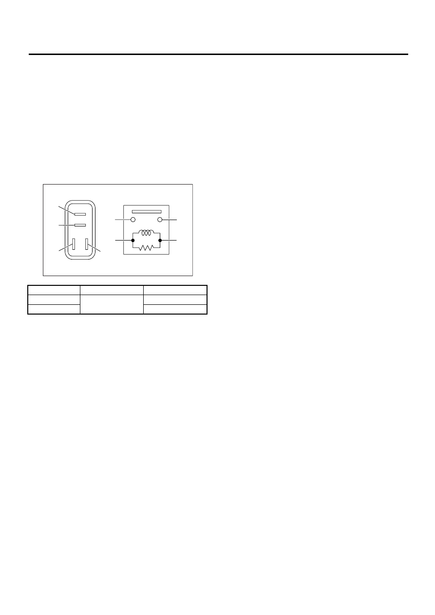
1. HORN RELAY
Measure horn relay resistance between terminals
(indicated in table below) while connecting terminal
No. 4 to battery positive terminal and terminal No. 3
to battery ground terminal.
Current
Terminal No.
Standard
Flow
1 and 2
Less than 1
Ω
No flow
More than 1 M
Ω
COM00001
(1)
(2)
(1)
(4)
(2)
(3)
(3)
(4)
COM-4
COMMUNICATION SYSTEM
HORN
3. Horn
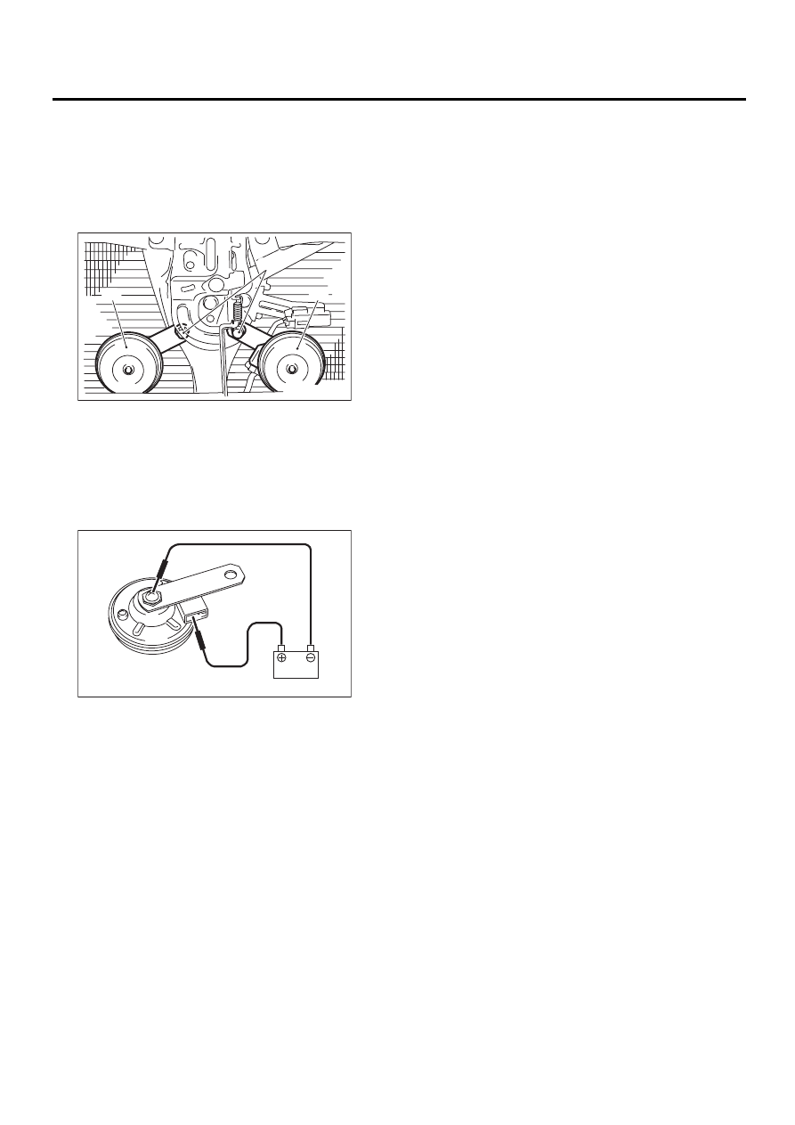
A: REMOVAL
1) Disconnect ground cable from battery.
2) Remove horn bracket mounting bolt (A).
3) Disconnect harness connector and remove horn
assembly (B).
B: INSTALLATION
Install in the reverse order of removal.
C: INSPECTION
With 12 V direct current supply between horn termi-
nal and case ground, check that the horn sounds
properly.
COM00007
( A )
( B )
( B )
COM00008
COM-5
COMMUNICATION SYSTEM
HORN SWITCH
4. Horn Switch
A: REMOVAL
WARNING:
Before servicing, be sure to read the notes in
the AB section for proper handling of the driver
airbag module. <Ref. to AB-3, CAUTION, Gen-
eral Description.>
1) Disconnect ground cable from battery.
2) Remove the driver's airbag module. <Ref. to
AB-12, Driver's Airbag Module.>
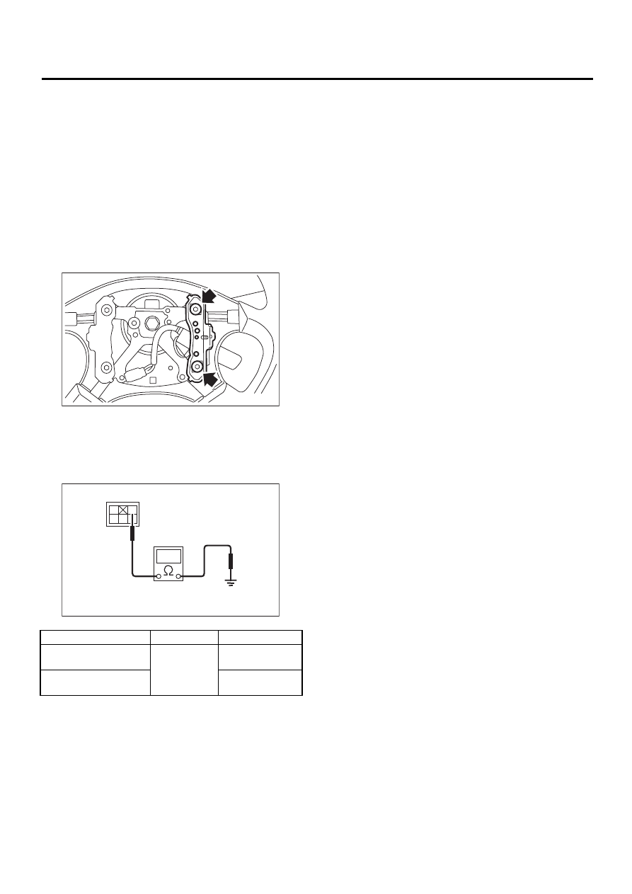
3) Remove horn switch from steering wheel as
shown.
B: INSTALLATION
Install in the reverse order of removal.
C: INSPECTION
Measure horn switch resistance.
Switch position
Terminal No.
Standard
When horn switch is
pushed.
1 and Body
ground
Less than 1
Ω
When horn switch is not
pushed.
More than 1 M
Ω
COM00004
COM00005
1
2
4
5
Нет комментариевНе стесняйтесь поделиться с нами вашим ценным мнением.
Текст