Subaru Legacy III (2000-2003 year). Service manual — part 478
EN(H4DOSTC)-82
ENGINE (DIAGNOSTICS)
DIAGNOSTIC PROCEDURE WITH DIAGNOSTIC TROUBLE CODE (DTC)
F: DTC P0103 — MASS OR VOLUME AIR FLOW CIRCUIT HIGH INPUT —
• TROUBLE SYMPTOM:
• Erroneous idling
• Engine stalls.
• Poor driving performance
CAUTION:
After repair or replacement of faulty parts, conduct Clear Memory Mode <Ref. to EN(H4DOSTC)-35,
OPERATION, Clear Memory Mode.> and Inspection Mode <Ref. to EN(H4DOSTC)-33, Inspection
Mode.> .
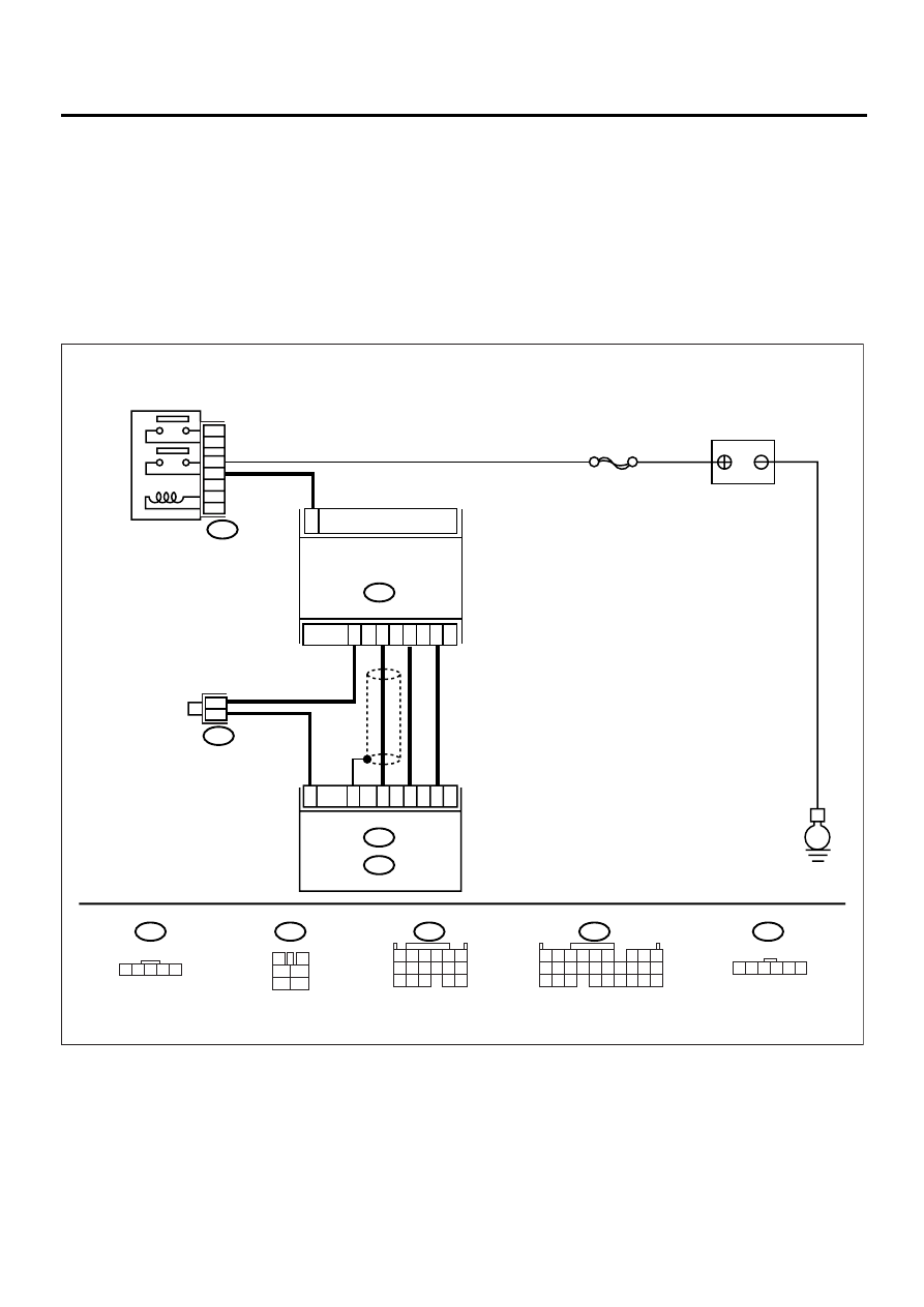
• WIRING DIAGRAM:
EN-00951
B122
B3
B135
5 6
7 8
2
1
9
4
3
10
24
22
23
25
11 12 13 14 15
26 27 28
16 17 18 19
20 21
BATTERY
E
B122
1
B3
MASS AIR FLOW AND
INTAKE AIR TEMPERATURE
ECM
B135
B :
B84
E :
SBF-5
1 2 3 4 5
3
4
1
2
5
6
1 2 3 4 5 6
B84
B47
2
6
2
4
3
5
E7
B27
E13
B19
E8
1 2 3
8 9 10
4
11 12
13 14 15
16
5 6
7
17
MAIN RELAY
B47
1
2
3
5
4
6

EN(H4DOSTC)-83
ENGINE (DIAGNOSTICS)
DIAGNOSTIC PROCEDURE WITH DIAGNOSTIC TROUBLE CODE (DTC)
Step
Value
Yes
No
1
CONNECT SUBARU SELECT MONITOR,
AND READ DATA.
1) Turn the ignition switch to OFF.
2) Connect the Subaru Select Monitor to data
link connector.
3) Turn the ignition switch to ON and Subaru
Select Monitor switch to ON.
4) Start the engine.
5) Read the data of mass air flow sensor sig-
nal using Subaru Select Monitor.
Is the measured value within the specified
value?
NOTE:
For detailed operation procedure, refer to the
“READ CURRENT DATA FOR ENGINE”. <Ref.
to EN(H4DOSTC)-26, Subaru Select Monitor.>
1.3 g/sec (0.172 lb/min) — 240
g/sec (32 lb/min) or 0.3 — 4.58
V
Even if MI lights
up, the circuit has
returned to a nor-
mal condition at
this time.
2
CHECK HARNESS BETWEEN ECM AND
MASS AIR FLOW SENSOR CONNECTOR.
1) Turn the ignition switch to OFF and Subaru
Select Monitor switch to OFF.
2) Disconnect the connector from mass air
flow sensor.
3) Turn the ignition switch to ON and Subaru
Select Monitor switch to ON.
4) Read the data of mass air flow sensor sig-
nal using Subaru Select Monitor.
Does the measured value exceed the spec-
ified value?
NOTE:
For detailed operation procedure, refer to the
“READ CURRENT DATA FOR ENGINE”. <Ref.
to EN(H4DOSTC)-26, Subaru Select Monitor.>
240 g/sec (32 lb/min) or 4.58 V Repair the battery
short circuit in har-
ness between
mass air flow sen-
sor and ECM con-
nector. After
repair, replace the
ECM.
Replace the mass
air flow sensor.
EN(H4DOSTC)-84
ENGINE (DIAGNOSTICS)
DIAGNOSTIC PROCEDURE WITH DIAGNOSTIC TROUBLE CODE (DTC)
G: DTC P0107 — MANIFOLD ABSOLUTE PRESSURE/BAROMETRIC PRES-
SURE CIRCUIT LOW INPUT —
CAUTION:
After repair or replacement of faulty parts, conduct Clear Memory Mode <Ref. to EN(H4DOSTC)-35,
OPERATION, Clear Memory Mode.> and Inspection Mode <Ref. to EN(H4DOSTC)-33, Inspection
Mode.> .
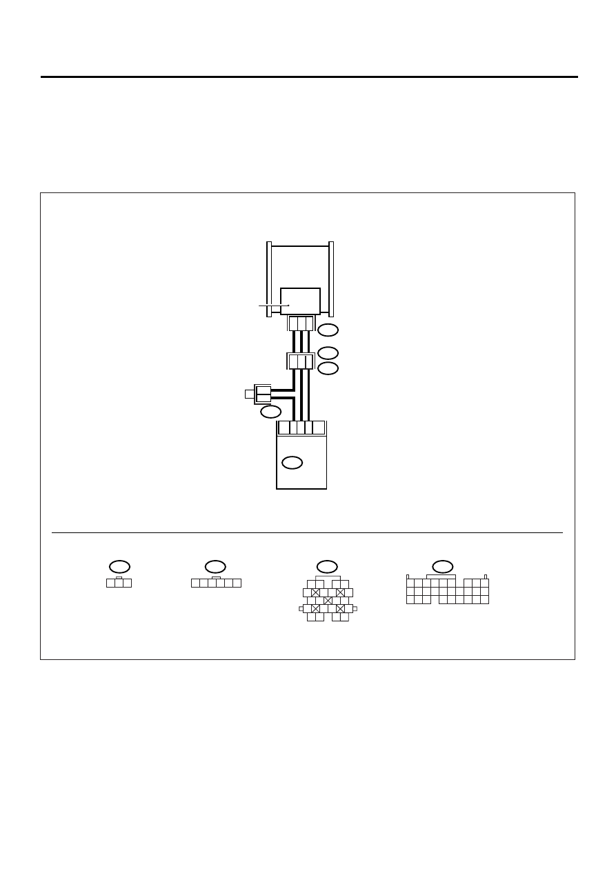
• WIRING DIAGRAM:
EN-00935
B122
PRESSURE SENSOR
THROTTLE BODY
3
2
1
19
9
8
ECM
B135
E21
E2
B21
1
6
20
18
16
1 2 3
B122
B21
E21
1 2 3 4 5 6
1 2
5
6 7
8
13
14 15
16
9 10
11 12
3 4
17 18
19 20
B135
5 6
7 8
2
1
9
4
3
10
24
22
23
25
11 12 13 14 15
26 27 28
16 17 18 19
20 21

EN(H4DOSTC)-85
ENGINE (DIAGNOSTICS)
DIAGNOSTIC PROCEDURE WITH DIAGNOSTIC TROUBLE CODE (DTC)
Step
Value
Yes
No
1
CHECK CURRENT DATA.
1) Start the engine.
2) Read the data of intake manifold absolute
pressure signal using Subaru Select Moni-
tor.
Is the measured value less than the speci-
fied value?
NOTE:
For detailed operation procedure, refer to the
“READ CURRENT DATA FOR ENGINE”. <Ref.
to EN(H4DOSTC)-26, Subaru Select Monitor.>
−
7.2 kPa (
−
54 mmHg,
−
2.1
inHg)
2
CHECK POOR CONTACT.
Check the poor contact in ECM and pressure
sensor connector.
Is there poor contact in ECM or pressure sen-
sor connector?
There is poor contact.
Repair the poor
contact in ECM or
pressure sensor
connector.
Even if MI lights
up, the circuit has
returned to a nor-
mal condition at
this time.
3
CHECK INPUT SIGNAL FOR ECM.
Measure the voltage between ECM connector
and chassis ground.
Connector & terminal
(B135) No. 9 (+) — Chassis ground (
−−−−
):
Does the measured value exceed the specified
value?
4.5 V
4
CHECK INPUT SIGNAL FOR ECM.
Measure the voltage between ECM connector
and chassis ground.
Connector & terminal
(B135) No. 9 (+) — Chassis ground (
−−−−
):
Does the measured value change by shaking
harness and connector of ECM while monitor-
ing the value with voltage meter?
The value changes.
Repair the poor
contact in ECM
connector.
Contact SUBARU
distributor service.
NOTE:
Inspection by DTM
is required, be-
cause probable
cause is deteriora-
tion of multiple
parts.
5
CHECK INPUT SIGNAL FOR ECM.
Measure the voltage between ECM and chas-
sis ground.
Connector & terminal
(B135) No. 8 (+) — Chassis ground (
−−−−
):
Is the measured value less than the specified
value?
0.7 V
Contact SUBARU
distributor service.
NOTE:
Inspection by DTM
is required, be-
cause probable
cause is deteriora-
tion of multiple
parts.
6
CHECK HARNESS BETWEEN ECM AND
PRESSURE SENSOR CONNECTOR.
1) Turn the ignition switch to OFF.
2) Disconnect the connector from pressure
sensor.
3) Turn the ignition switch to ON.
4) Measure the voltage between pressure
sensor connector and engine ground.
Connector & terminal
(E21) No. 3 (+) — Engine ground (
−−−−
):
Does the measured value exceed the spec-
ified value?
4.5 V
Repair the open
circuit in harness
between ECM and
intake manifold
pressure sensor
connector.
Нет комментариевНе стесняйтесь поделиться с нами вашим ценным мнением.
Текст