Subaru Legacy III (2000-2003 year). Service manual — part 488
EN(H4DOSTC)-122
ENGINE (DIAGNOSTICS)
DIAGNOSTIC PROCEDURE WITH DIAGNOSTIC TROUBLE CODE (DTC)
S: DTC P0246 — TURBO/SUPER CHARGERWASTEGATESOLENOID “A” HIGH
—
• TROUBLE SYMPTOM:
• Erroneous idling
CAUTION:
After repair or replacement of faulty parts, conduct Clear Memory Mode <Ref. to EN(H4DOSTC)-35,
OPERATION, Clear Memory Mode.> and Inspection Mode <Ref. to EN(H4DOSTC)-33, Inspection
Mode.> .
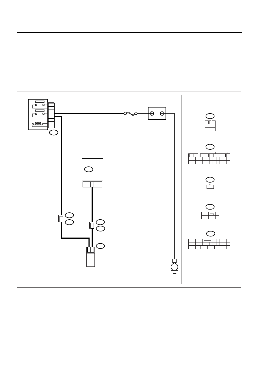
• WIRING DIAGRAM:
EN-00938
MAIN RELAY
B47
1
2
3
5
4
6
BATTERY
E
B47
B137
F81
F44
B137
F81
WASTEGATE
CONTROL SOLENOID
VALVE
ECM
24
1
2
SBF-5
3
4
1
2
5
6
1
2
7
8
9
5
6
3
4
10 11 12
19 20 21
29 30 31
13 14 15 16 17
27 28
18
22 23 24 25 26
1 2
B62
F45
B62
B61
F44
1
5
21
9
32
1 2 3 4
5 6
10 11 12 13 14 15
7
16
23
30
19 20
22
26 27 28 29
8
17
24
31
18
25
1 2
3
4 5 6 7 8

EN(H4DOSTC)-123
ENGINE (DIAGNOSTICS)
DIAGNOSTIC PROCEDURE WITH DIAGNOSTIC TROUBLE CODE (DTC)
Step
Value
Yes
No
1
CHECK OUTPUT SIGNAL FROM ECM.
1) Turn the ignition switch to ON.
2) Measure the voltage between ECM and
chassis ground.
Connector & terminal
(B137) No. 24 (+) — Chassis ground (
−−−−
):
Does the measured value exceed the spec-
ified value?
10 V
2
CHECK POOR CONTACT.
Check poor contact in ECM connector.
Is there poor contact in ECM connector?
There is poor contact.
Repair the poor
contact in ECM
connector.
Replace the ECM.
<Ref. to
FU(H4DOSTC)-
40, Engine Con-
trol Module.>
3
CHECK HARNESS BETWEEN WASTEGATE
CONTROL SOLENOID VALVE AND ECM
CONNECTOR.
1) Turn the ignition switch to OFF.
2) Disconnect the connector from wastegate
control solenoid valve.
3) Turn the ignition switch to ON.
4) Measure the voltage between ECM and
chassis ground.
Connector & terminal
(B137) No. 24 (+) — Chassis ground (
−−−−
):
Does the measured value exceed the spec-
ified value?
10 V
Repair the battery
short circuit in har-
ness between
ECM and waste-
gate control sole-
noid valve
connector. After
repair, replace the
ECM. <Ref. to
FU(H4DOSTC)-
40, Engine Con-
trol Module.>
4
CHECK WASTEGATE CONTROL SOLE-
NOID VALVE.
1) Turn the ignition switch to OFF.
2) Measure the resistance between wastegate
control solenoid valve terminals.
Terminals
No. 1 — No. 2:
Is the measured value less than the speci-
fied value?
1
Ω
Replace the
wastegate control
solenoid valve
<Ref. to
IN(H4DOSTC)-21,
Wastegate Con-
trol Solenoid
Valve.> and ECM
<Ref. to
FU(H4DOSTC)-
40, Engine Con-
trol Module.>
5
CHECK POOR CONTACT.
Check poor contact in ECM connector.
Is there poor contact in ECM connector?
There is poor contact.
Repair the poor
contact in ECM
connector.
Replace the ECM.
<Ref. to
FU(H4DOSTC)-
40, Engine Con-
trol Module.>
EN(H4DOSTC)-124
ENGINE (DIAGNOSTICS)
DIAGNOSTIC PROCEDURE WITH DIAGNOSTIC TROUBLE CODE (DTC)
T: DTC P0249 — TURBO/SUPER CHARGERWASTEGATESOLENOID “B” LOW
—
• TROUBLE SYMPTOM:
• Poor driving performance
CAUTION:
After repair or replacement of faulty parts, conduct Clear Memory Mode <Ref. to EN(H4DOSTC)-35,
OPERATION, Clear Memory Mode.> and Inspection Mode <Ref. to EN(H4DOSTC)-33, Inspection
Mode.> .
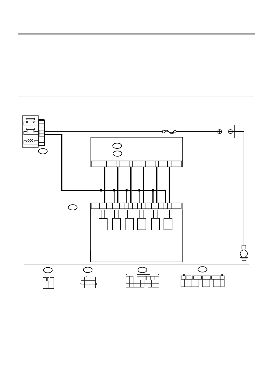
• WIRING DIAGRAM:
EN-00939
B220
B47
E
BATTERY
MAIN RELAY
3
B136
ECM
SBF-5
5
2
1
4
6
B47
3
4
1
2
5
6
B220
SOLENOID
BOX ASSY
1
2
3
4
5
6
7
8
9
10
11
12
(A)
(B)
(C)
(D)
(E)
(F)
(A): RELIEF VALVE SOLENOID 2
(B): RELIEF VALVE SOLENOID 1
(C): EXHAUST VALVE CONTROL SOLENOID VALVE
(NEGATIVE PRESSURE)
(D): EXHAUST VALVE CONTROL SOLENOID VALVE
(POSITIVE PRESSURE)
(E): INTAKE AIR CONTROL SOLENOID VALVE
(F): EXHAUST VALVE CONTROL DUTY SOLENOID VALVE
C:
B137
D:
C11
C12
C3
C1
D22
D11
1 2 3 4
5 6 7 8
9 10 11 12
B136
1 2
7
8 9
5
6
3
4
10 11 12
19 20 21
13 14 15 16
17 18
22 23 24
B137
1
2
7
8
9
5
6
3
4
10 11 12
19 20 21
29 30 31
13 14 15 16 17
27 28
18
22 23 24 25 26

EN(H4DOSTC)-125
ENGINE (DIAGNOSTICS)
DIAGNOSTIC PROCEDURE WITH DIAGNOSTIC TROUBLE CODE (DTC)
Step
Value
Yes
No
1
CHECK INPUT SIGNAL TO ECM.
1) Turn the ignition switch to ON.
2) Measure the voltage between ECM and
chassis ground.
Connector & terminal
(B137) No. 11 (+) — Chassis ground (
−−−−
):
Does the measured value exceed the spec-
ified value?
10 V
Even if MI lights
up, the circuit has
returned to a nor-
mal condition at
this time. Contact
SUBARU distribu-
tor service.
NOTE:
Inspection by DTM
is required, be-
cause probable
cause is deteriora-
tion of multiple
parts.
2
CHECK HARNESS BETWEEN EXHAUST
VALVE CONTROL DUTY SOLENOID VALVE
AND ECM CONNECTOR.
1) Turn the ignition switch to OFF.
2) Disconnect the connectors from exhaust
valve control duty solenoid valve and ECM.
3) Measure the resistance of harness
between exhaust valve control duty sole-
noid valve connector and engine ground.
Connector & terminal
(B220) No. 12 — Engine ground:
Does the measured value exceed the spec-
ified value?
1 M
Ω
Repair the ground
short circuit in har-
ness between
ECM and exhaust
valve control duty
solenoid valve
connector.
3
CHECK HARNESS BETWEEN EXHAUST
VALVE CONTROL DUTY SOLENOID VALVE
AND ECM CONNECTOR.
Measure the resistance of harness between
ECM and exhaust valve control duty solenoid
valve of harness connector.
Connector & terminal
(B137) No. 11 — (B220) No. 12:
Is the measured value less than the specified
value?
1
Ω
Repair the open
circuit in harness
between ECM and
exhaust valve con-
trol duty solenoid
valve connector.
4
CHECK EXHAUST VALVE CONTROL DUTY
SOLENOID VALVE.
Measure the resistance between purge control
solenoid valve terminals.
Terminals
No. 11 — No. 12:
Is the measured value within the specified
value?
17 — 21
Ω
Replace the
exhaust valve con-
trol duty solenoid
valve. <Ref. to
IN(H4DOSTC)-19,
Solenoid Box
Assembly.>
5
CHECK POWER SUPPLY TO EXHAUST
VALVE CONTROL DUTY SOLENOID VALVE.
1) Turn the ignition switch to ON.
2) Measure the voltage between exhaust
valve control duty solenoid valve and
engine ground.
Connector & terminal
(B220) No. 11 (+) — Engine ground (
−−−−
):
Does the measured value exceed the spec-
ified value?
10 V
Repair the open
circuit in harness
between main
relay and exhaust
valve control duty
solenoid valve
connector.
Нет комментариевНе стесняйтесь поделиться с нами вашим ценным мнением.
Текст