Subaru Legacy III (2000-2003 year). Service manual — part 74
CO(H4SO)-4
COOLING
GENERAL DESCRIPTION
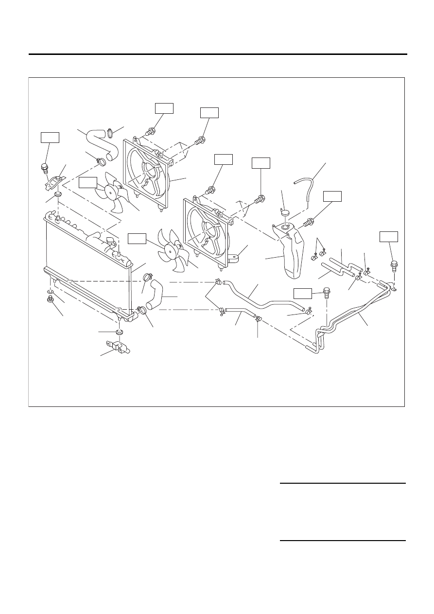
2. RADIATOR AND RADIATOR FAN
(1) Radiator lower cushion
(12) Main fan shroud
(19) ATF inlet hose B (AT vehicles
only)
(2) Radiator
(13) Radiator main fan and main fan
motor ASSY
(3) Radiator upper cushion
(20) Radiator outlet hose
(4) Radiator upper bracket
(14) ATF hose clamp (AT vehicles
only)
(21) Radiator drain plug
(5) Clamp
(22) O-ring
(6) Radiator inlet hose
(15) ATF inlet hose A (AT vehicles
only)
(23) Radiator lower bracket
(7) Engine coolant reservoir tank cap
(8) Overflow hose
(16) ATF outlet hose A (AT vehicles
only)
Tightening torque: N·m (kgf-m, ft-lb)
(9) Engine coolant reservoir tank
T1: 4.4 (0.45, 3.3)
(10) Sub fan shroud
(17) ATF pipe (AT vehicles only)
T2: 12 (1.2, 8.7)
(11) Radiator sub fan and sub fan
motor ASSY
(18) ATF outlet hose B (AT vehicles
only)
T3: 18 (1.8, 13.0)
T4: 3.4 (0.35, 2.5)
T5: 4.9 (0.50, 3.6)
(19)
(15)
(14)
(14)
(14)
(14)
(14)
(14)
( 7 )
( 8 )
CO-00081
T5
T5
T2
T2
T1
T1
T4
T4
T3
T5
( 1 )
( 2 )
( 3 )
( 4 )
( 5 )
( 5 )
( 5 )
( 5 )
( 6 )
( 9 )
(10)
(11)
(12)
(13)
(16)
(17)
(18)
(20)
(21)
(22)
(23)
CO(H4SO)-5
COOLING
GENERAL DESCRIPTION
C: CAUTION
• Wear working clothing, including a cap, protec-
tive goggles, and protective shoes during opera-
tion.
• Remove contamination including dirt and corro-
sion before removal, installation or disassembly.
• Keep the disassembled parts in order and pro-
tect them from dust or dirt.
• Before removal, installation or disassembly, be
sure to clarify the failure. Avoid unnecessary re-
moval, installation, disassembly, and replacement.
• Be careful not to burn your hands, because each
part in the vehicle is hot after running.
• Be sure to tighten fasteners including bolts and
nuts to the specified torque.
• Place shop jacks or safety stands at the specified
points.
• Before disconnecting electrical connectors of
sensors or units, be sure to disconnect ground ca-
ble from battery.
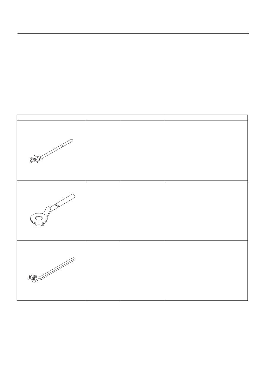
D: PREPARATION TOOL
ILLUSTRATION
TOOL NUMBER
DESCRIPTION
REMARKS
499977100
CRANKSHAFT PUL-
LEY WRENCH
Used for fixing crankshaft pulley when loos-
ening and tightening crankshaft pulley bolts.
(2500 cc model)
499977400
CRANKSJAFT PUL-
LEY WRENCH
Used for fixing crankshaft pulley when loos-
ening and tightening crankshaft pulley bolts.
(2000 cc model)
18231AA010
CAMSHAFT
SPROCKET
WRENCH
• Used for removing and installing camshaft
sprocket.
• Camshaft sprocket wrench (499207100) is
also available.
ST-499977100
ST-499977400
ST18231AA010
CO(H4SO)-6
COOLING
RADIATOR MAIN FAN SYSTEM
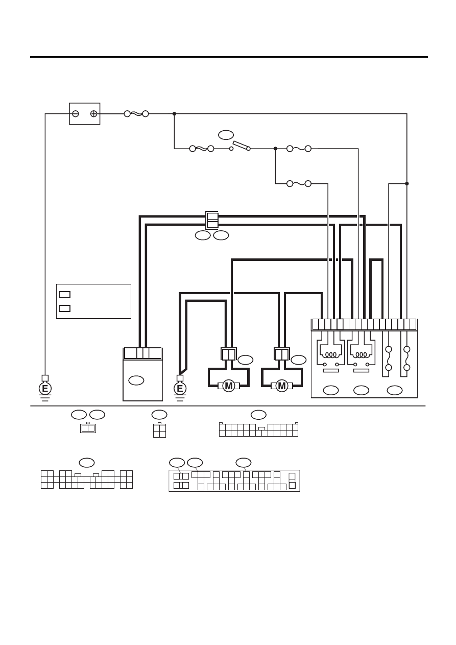
2. Radiator Main Fan System
A: SCHEMATIC
CO-00169
2
1
4
3
21
22
24
20
8
7
5
9
20A
20A
SUB FAN
RELAY
AIR CONDITIONING RELAY HOLDER
SUB FAN
MOTOR
MAIN FAN
MOTOR
MAIN FAN
RELAY
F28
F16
F66
F27
1
2
F17
B100
F2
B72
1
2
NO. 18
NO. 17
SBF-4
SBF-1
IGNITION
SWITCH
B72
3 4
1 2
B134
1 2
3 4
5 6
7 8
9 10 11 12 13 14 15 16 17 18 19 20 21 22 23
24 25
26 27 28 29
30 31 32 33
34 35
BATTERY
B134
ECM
F16
F17
2 1
F27
1
2
3
4
5 6 7
8
9
11
10
13
12
14
21
20
23
22
24
31
30
33
32
34
16
15
17
18
19
26
25
27
28
29
35
36
F66
F28
: 14
: 3
: 13
: 12
WITH OBD
WITHOUT OBD
1
*
2
*
WITH OBD
WITHOUT OBD
1
*
2
*
7
6
F2
3 4
1 2
8 9 10 11
12 13 14 15 16 17 18 19 20 21 22 23 24
5 6
7

CO(H4SO)-7
COOLING
RADIATOR MAIN FAN SYSTEM
B: INSPECTION
DETECTING CONDITION:
Condition:
• Engine coolant temperature is above 95
°
C (203
°
F).
• Vehicle speed is below 19 km/h (12 MPH).
TROUBLE SYMPTOM:
• Radiator main fan does not rotate under the above conditions.
Step
Value
Yes
No
1
CHECK POWER SUPPLY TO MAIN FAN MO-
TOR.
CAUTION:
Be careful not to overheat engine during re-
pair.
1) Turn ignition switch to OFF.
2) Disconnect connector from main fan motor.
3) Start the engine, and warm it up until
engine coolant temperature increases over
95
°
C (203
°
F).
4) Stop the engine and turn ignition switch to
ON.
5) Measure voltage between main fan motor
connector and chassis ground.
Connector & terminal
(F17) No. 2 (+) — Chassis ground (
−−−−
):
Does the measured value exceed the spec-
ified value?
10 V
2
CHECK GROUND CIRCUIT OF MAIN FAN
MOTOR.
1) Turn ignition switch to OFF.
2) Measure resistance between main fan
motor connector and chassis ground.
Connector & terminal
(F17) No. 1 — Chassis ground:
Is the measured value less than the speci-
fied valve?
5
Ω
Repair open circuit
in harness
between main fan
motor connector
and chassis
ground.
3
CHECK POOR CONTACT.
Check poor contact in main fan motor connec-
tor.
Is there poor contact in main fan motor con-
nector?
There is poor contact.
Repair poor con-
tact in main fan
motor connector.
4
CHECK MAIN FAN MOTOR.
Connect battery positive (+) terminal to termi-
nal No. 2, and negative (
−
) terminal to terminal
No. 1 of main fan motor connector.
Does the main fan rotate?
The main fan rotates.
Repair poor con-
tact in main fan
motor connector.
Replace main fan
motor with a new
one.
5
CHECK POWER SUPPLY TO MAIN FAN RE-
LAY.
1) Turn ignition switch to OFF.
2) Remove main fan relay from A/C relay
holder.
3) Measure voltage between main fan relay
terminal and chassis ground.
Connector & terminal
(F66) No. 8 (+) — Chassis ground (
−−−−
):
Does the measured value exceed the spec-
ified value?
10 V
Нет комментариевНе стесняйтесь поделиться с нами вашим ценным мнением.
Текст